ENGLISH
SERVICE MANUAL
42
909 6424 000(3)2007-12 BR 601 / BR 651 / BR 751 / BR 751 C
RECOVERY WATER SYSTEM
VACUUM SYSTEM MOTOR DISASSEMBLY/ASSEMBLY (before S/N ..........)
Disassembly
Drive the machine to the appointed disposal area, and empty the recovery water tank (58) with the hose (22).
Empty the solution/washing water tank (59) with the tap (36).
Drive the machine on a level fl oor.
Turn the ignition key (12) to "0".
Disconnect the vacuum hose (23) from the squeegee (24).
Carefully lift the tank assembly (60).
Disconnect the battery connector (63).
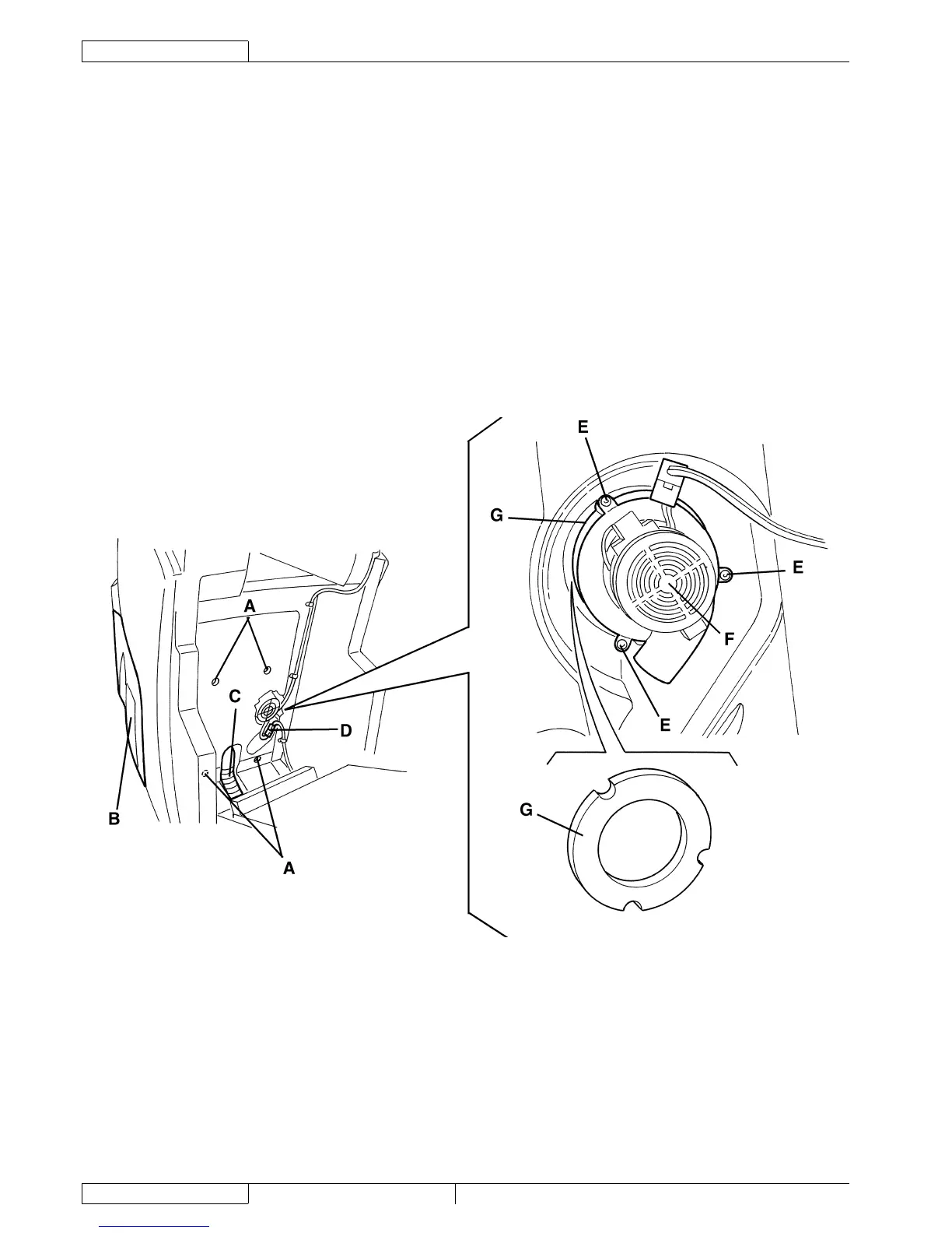
Disconnect the connector (D) from the vacuum system motor.
Remove the screws (A), then remove the recovery water tank (B) with the vacuum hose (C).
Remove the screws (E).
Remove the vacuum system motor (F).
Recover the gasket (G).
Assembly
Assemble the components in the reverse order of disassembly, and note the following:
Check the gasket (G) for integrity and effi ciency, otherwise replace it.
S301338
1.
2.
3.
4.
5.
6.
7.
8.
9.
10.
11.
12.
13.
•





 To Next Page