SERVICE MANUAL
ENGLISH
BR 601 / BR 651 / BR 751 / BR 751 C 909 6424 000(3)2007-12
65
DRIVE SYSTEM
DRIVE SYSTEM MOTOR, BEARING AND GASKET DISASSEMBLY/ASSEMBLY (Machines after
January 2007)
Disassembly
Drive the machine to the appointed disposal area, and empty the recovery water tank (58) with the hose (22).
Empty the washing water tank (59) with the tap (36).
Place the machine on a hoisting system (if available).
Otherwise, drive the machine on a level fl oor.
Turn the ignition key (12) to "0".
Remove the brush/pad-holder deck (16) or the cylindrical brush deck (17) (see the procedure in the relevant paragraph).
Turn the front wheel (AG) completely to the left.
Apply proper wedges to right and left rear wheels (43), so that the machine cannot move when the front wheel (AG) is lifted.
With the help of an assistant, slightly lift the front part of the machine and apply to the frame brackets (AH) two proper wooden
shims (AI) high enough to keep the front wheel (AG) lifted for about 1.18 in (3 cm) from the fl oor.
Lift the tank assembly (60) and disconnect the battery connector (63).
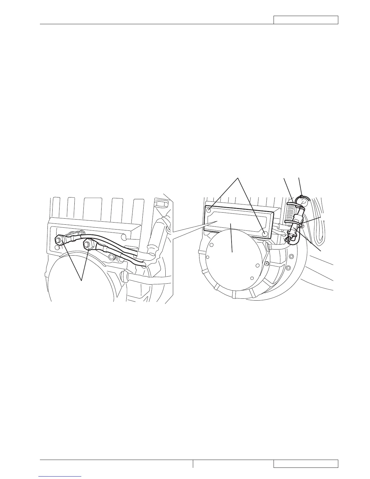
Remove the wiring harness fastening clamp (A).
Cut the fastening clamps (B) of the connector (C).
Disconnect the electromagnetic brake connector (C).
Remove the screws (D), then remove the cover (E).
Disconnect the electrical connections (F).
F
D
E
C
A
B
B
S301643
1.
2.
3.
4.
5.
6.
7.
8.
9.
10.
11.
12.
13.
14.