SERVICE MANUAL
ENGLISH
BR 601 / BR 651 / BR 751 / BR 751 C 909 6424 000(3)2007-12
71
DRIVE SYSTEM
SPEED REDUCTION SENSOR REPLACEMENT
Disassembly
Remove the front fairing (see the procedure in the relevant paragraph).
Remove the nuts (93), then remove the cover (92).
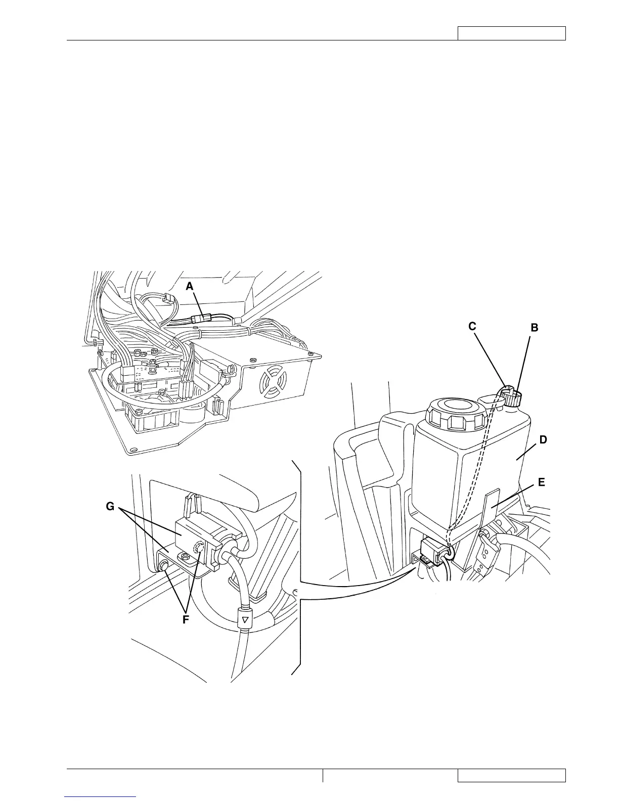
Slightly move the electrical component panel (100).
Disconnect the speed reduction sensor connector (A).
If equipped, unscrew the fi tting (B) and remove the hose (C) from the detergent tank (D); then remove the detergent tank (D)
by disengaging it from the fastener (E).
If equipped, remove the screws (F) and move the detergent pump with the support (G).
Remove two mounting screws (H) of the foot board (I).
Lift the foot board (J) and remove the sensor cable (K) through the passage (L).
Remove the nuts (M), then remove the speed reduction sensor (N) with the cable.
Assembly
Assemble the components in the reverse order of disassembly, and note the following:
Insert the speed reduction sensor wiring harness (O) with the connector (P) disconnected; then connect the wiring harness
to the connector (P), paying attention to the cable colours.
Adjust the speed reduction sensor (see the procedure in the relevant paragraph).
S301352
1.
2.
3.
4.
5.
6.
7.
8.
9.
10.
•
•