NIRStar 14.1 - User Manual
Page 119 of 124
The 6-step method for generating a channel layout is straightforward to implement for nearly any
optode array. A possible downside is that it can lead you to generate a grid containing large numbers of
rows and columns (10 and 14 for the example above), with only a small percentage of the grid cells
occupied by channels (26 out of 140, or ~19%). Once you have attained proficiency in generating layouts
this way, you may want to experiment with collapsing rows and/or columns, on a freehand, case-by-case
basis, in order to achieve a smaller grid size (while sacrificing some spatial accuracy in the channel
locations). One way in which this sort of grid-size economy can be achieved for the optode array we are
considering here would be:
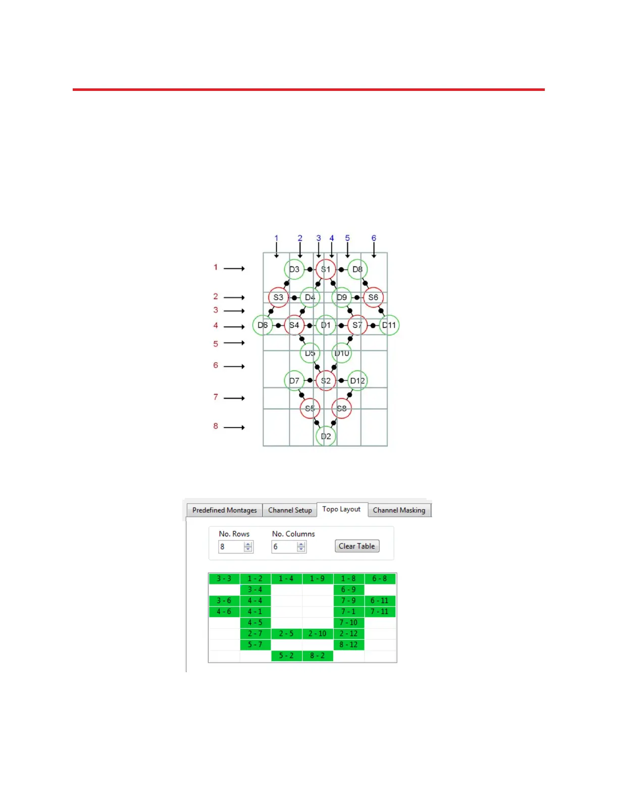
Figure 104: Freehand example, arranging channels more economically on an irregular grid.
This corresponds to the following 8×6 Topo Layout, which has channels in more than half of the grid:
Figure 105: Layout editor entry corresponding to the previous example.