NIRStar 14.1 - User Manual
Page 32 of 124
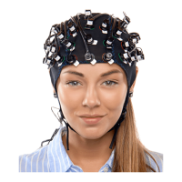
The Layout Editor offers a convenient way of specifying the spatial arrangement of specific source-
detector-combinations (‘channels’). As illustrated in Figure 15 and in Figure 16, the physical layout on the
head (in this example, referenced to the international 10-10 system) is transferred to a tabular rectilinear
view. The channel formed by Source X and Detector Y is identified by the String X-Y in the appropriate
field.
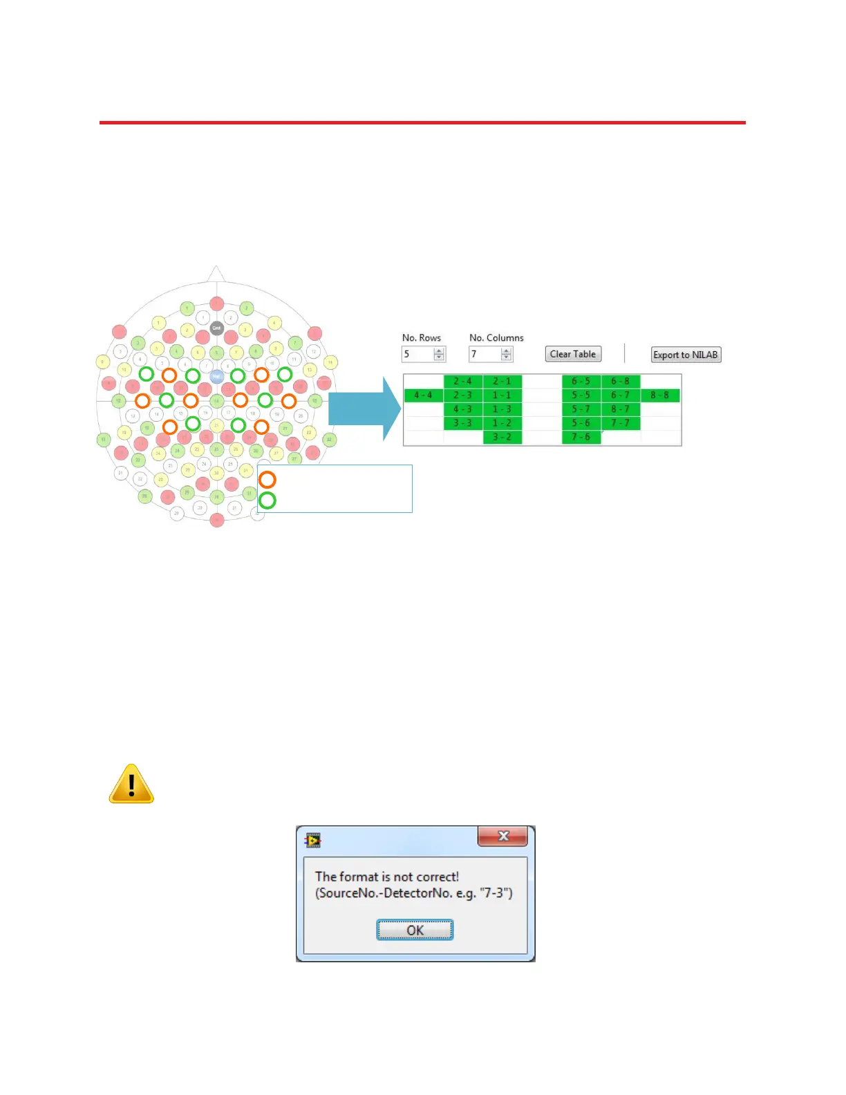
To define the layout, click on a cell of the table and enter the specific channel identifier. A channel is
defined by specifying first the source number, followed by a minus sign, followed by the detector
number. If the format requirement “Source No. - Detector No.” is not met, an error message is displayed
as shown in Figure 17. The number of rows and the number of columns can be adjusted by using the
appropriate fields in the upper left corner of the Topo Layout user interface.
Please refer to Appendix B for a simple algorithm on how to generate a rectilinear
abstraction for most any real-world probe arrangement.
Figure 16. Example configuration illustrating how to translate a physical source-detector arrangement on the
head to the topographic layout. The physical setup is shown in relation to the positions of the EEG 10-10 system.
Each neighboring source-detector combination forms a measurement channel. For example, the channel defined
by source 2 and detector 4 would be positioned top left in the topographic layout.
1
8
5
6
3
2
1
4
7
4
3
2
6
5
7
8
1
8
5
6
3
2
1
4
7
4
3
2
6
5
7
8
1
1
Source No. 1, etc…
Detector No. 1, etc…
1
1
Source No. 1, etc…
Detector No. 1, etc…
Figure 17. Error message for an inappropriate format of the source-detector definition.