prw2101a0600p_01
17 / 105
4. ELECTRICAL CONNECTION
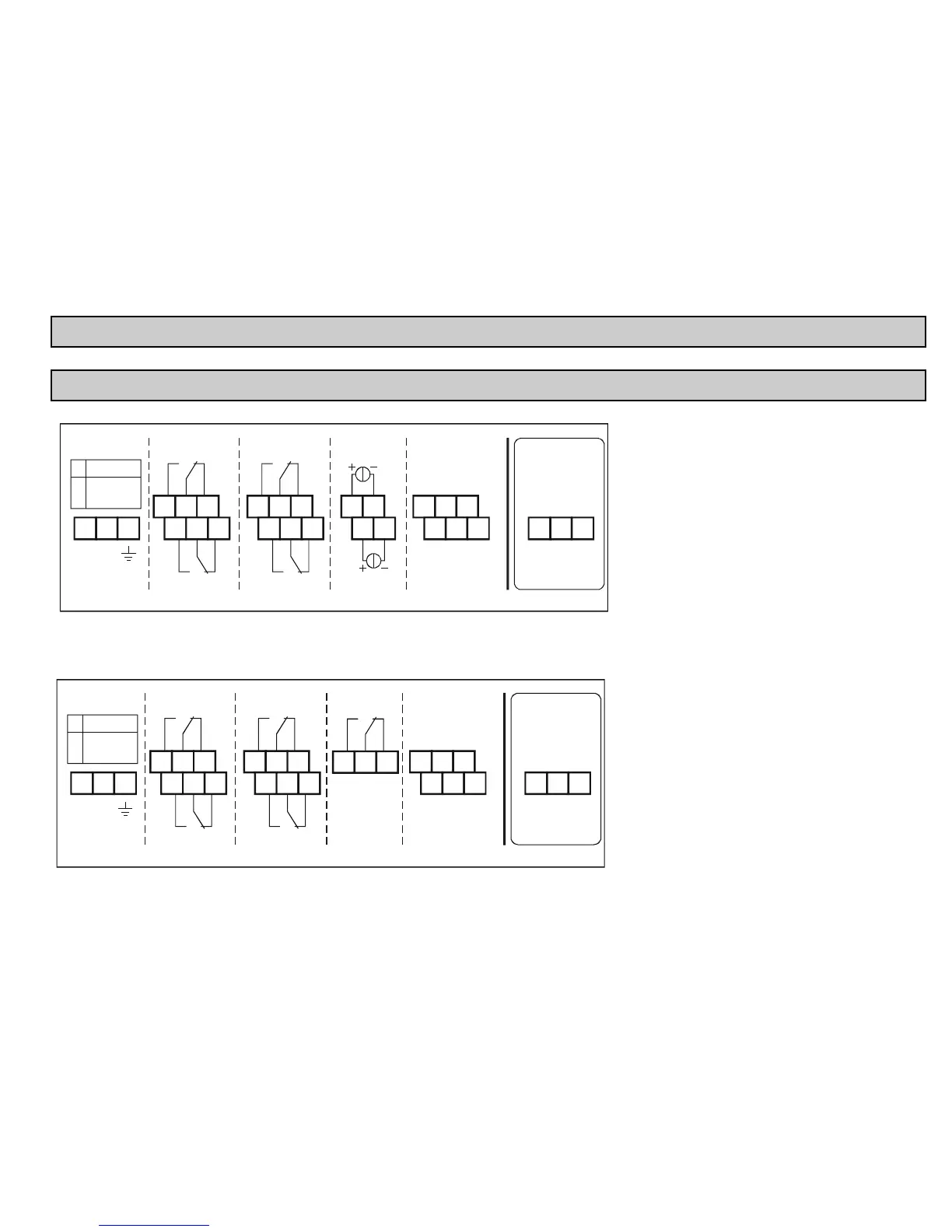
4.1. ARRANGEMENT OF THE CABLE TERMINALS
4.1.1. Four relays version
1 2 3
4 5 6
7 8 9
16 17
18 19
10 11 12
13 14 15
20 21 22
23 24 25
MAINS RELAY 1
RELAY 2
RELAY 3
RELAY 4
CURRENT
OUT 1
CURRENT
OUT 2
USER RS485
MODULE RS485
ABCOM
ABCOM
DEVICES
26 27 28
LLSH+
-
11.4 ... 28V
AC
11.4 ... 40V
DC
85 ... 255V
AC
()
+
-()
**
*
After loosening and removing screws fastening the
cover the cables can be connected. The same cable
should not be used for AC and DC as well as for SELV
and mains voltage.
For wiring of the transmitters shielded, twisted cable
pair (STP) should be used with the length depending
on the number of connected units and the electrical
properties of cable.
RS485 interface: A: TRD+
B: TRD–
COM: shielding
* Only PR types
** Non-Ex versions only
4.1.2. Five relays version
1 2 3
4 5 6
7 8 9
10 11 12
13 14 15
20 21 22
23 24 25
MAINS RELAY 1
RELAY 2
RELAY 3
RELAY 4
RELAY 5
USER RS485
MODULE RS485
ABCOM
ABCOM
DEVICES
26 27 28
LLSH+
-
11.4 ... 28V
AC
11.4 ... 40V
DC
85 ... 255V
AC
()
+
-()
16 17 18