11. Module reference: In/Out group NORD MODULAR G2 V1.1
Page 110
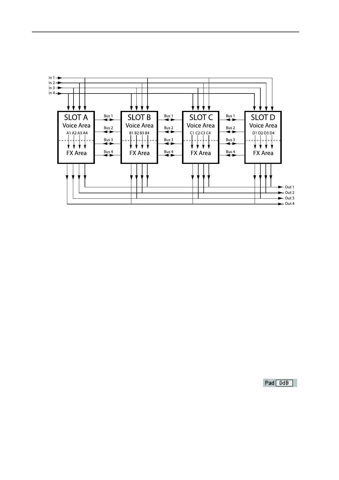
you like. In the figure below, the different audio signal channels in the Nord Modular G2 system are de-
scribed:
N
NN
N
O
OO
OT
TT
TE
EE
ES
SS
S
A
AA
AB
BB
BO
OO
OU
UU
UT
TT
T
U
UU
US
SS
SI
II
IN
NN
NG
GG
G
T
TT
TH
HH
HE
EE
E
A
A A
A
U
UU
UD
DD
DI
II
IO
OO
O
I
I I
I
N
NN
N
S
SS
SO
OO
OU
UU
UR
RR
RC
CC
CE
EE
ES
SS
S
The ‘In’ selector routes line level audio signals from the I
N
1-4 inputs on the rear panel of Nord Modular
G2 to your patch. You can also use a dynamic microphone in the XLR M
IC
I
NPUT
on the rear panel.
This input has a built-in preamp and you control the input gain with the M
IC
G
AIN
knob on the front
panel. If you use a dynamic microphone in the XLR M
IC
I
NPUT
, the line level I
N
1 jack will automati-
cally be disabled. The M
IC
I
NPUT
signal can then be patched from the Out 1 (or L) output of the Input
modules. A total of four separate audio signals can be patched into the system at a time.
If you use the I
N
1-4 inputs it’s important that you amplify the input signals to line level externally to get
good sound quality. If you put in too low a signal and amplify it, using for example the Pad scroll button
or the Amplifter module, the sound quality won’t be good. The reason for this is that the internal ampli-
fication is digital, and a low analog input signal will result in low resolution. A low resolution signal that
is digitally amplified will sound distorted.
Note: If you want to process a stereo input signal, any processing modules (filters etc.) has to be dupli-
cated in the patch and process one “channel” each.
P
PP
P
A
AA
AD
DD
D
The Pad scroll button on the Input and Output modules can be used to attenuate or
amplify the signals. On the Input modules you can select between 0dB, -6dB, -12dB
and +6dB and on the Output modules between 0dB, +6dB, +12dB and +18dB.
Note that the four audio Bus channels are parallel and
can be used by Patches in the Slots in no specific order.