11. Module reference: Switch group NORD MODULAR G2 V1.1
Page 164
2. Now, click on the In 2 button of the 8-1Switch and note that the second LED of the 1-8Mux is lit.
3. Click on the In 8 button of the 8-1Switch and note that the last LED of the 1-8Mux is lit instead.
The special thing about this Ctrl signal is that it’s defined by the different “states” of the Switch mod-
ule, i.e. which Channel Select button is currently depressed. The Switch module sends out the Ctrl
signal value 0 for the initial state (no button or button 1 depending on type of Switch module), value
4 for the next state, value 8 for the next and so on. The maximum Ctrl signal value a Switch module
can send is 28 when button number 8 is selected on an 8-1Switch or 1-8Switch module. The Ctrl
input on the 8-1Mux and 1-8Mux modules responds according to these Ctrl signal ranges: 0<4 =
channel 1 active, 4<8 = channel 2 active, 8<12 = channel 3 active and so on up to 28 and above, which
will activate channel 8. The reason for this pre-defined Ctrl value ranges is that a Switch module but-
ton should always correspond to the same channel number on a Mux module, regardless of number
of buttons/channels on the module.
I
II
I
N
NN
NP
PP
PU
UU
UT
TT
TS
SS
S
All Mixer module inputs are Dynamic Control/Audio signal inputs. This means
they adapt the module bandwidth to the bandwidth of the incoming signal(s). As
soon as you patch an audio signal to one input, the entire Mixer module will au-
tomatically “update” to Audio bandwidth for highest possible quality. This also results in the module us-
ing more Patch Load.
O
OO
O
U
UU
UT
TT
TP
PP
PU
UU
UT
TT
T
(
((
(
S
SS
S
)
))
)
Dynamic Control/Audio depending on the input signals. Signal: Bipolar
C
CC
C
H
HH
HA
AA
AN
NN
NN
NN
NE
EE
EL
LL
L
S
S S
S
E
EE
EL
LL
LE
EE
EC
CC
CT
TT
T
R
RR
RA
AA
AD
DD
DI
II
IO
OO
O
B
BB
BU
UU
UT
TT
TT
TT
TO
OO
ON
NN
NS
SS
S
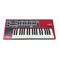
Most Switch modules feature radio buttons to select channel. A blue Channel Se-
lect button means that the channel is enabled and all other channels are disabled.
These Channel Select buttons can also be labelled for better overview. Right-click
on a Channel Select button and select ‘Edit name’. Type in the new name and press Enter. Note that the
name cannot be longer than 7 characters because of the size of the A
SSIGNABLE
D
ISPLAYS
on the synth.
The Channel Select radio buttons cannot be assigned to a Morph Group.
S
SS
S
W
WW
W
O
OO
O
N
NN
N
O
OO
O
F
FF
FF
FF
F
M
MM
M
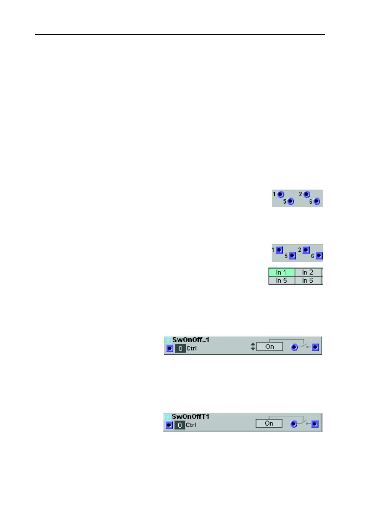
The Momentary OnOff Switch is per-
fect for manual triggering of different
things in the Patch - especially when you
assign the On button to an A
SSIGNABLE
B
UTTON
on the synth panel. When you click the On button,
the switch “closes” for just a brief moment and then automatically “opens” again. If no signal is patched
to the input, the output will send the value 64 units when the switch closes. See also "Common Switch
parameters”.
S
SS
S
W
WW
W
O
OO
O
N
NN
N
O
OO
O
F
FF
FF
FF
F
T
TT
T
The Toggling OnOff Switch is perfect
for manual activating different things in
the Patch - especially when you assign
the On button to an A
SSIGNABLE
B
UTTON
on the synth panel. When you click the On button, the
switch “closes” and when you click again the switch “opens”. If no signal is patched to the input, the out-
put will send the value 64 units when the switch closes. See also "Common Switch parameters”.