NORD MODULAR G2 V1.1 11. Module reference: Logic group
Page 177
L
LL
L
O
OO
OG
GG
GI
II
IC
CC
C
G
GG
GR
RR
RO
OO
OU
UU
UP
PP
P
These modules can modulate and generate logic signals in a number of different ways. A logic signal can
have two states: high, which corresponds to a value of +64 units and low, which corresponds to 0 units.
Read more about logic signals in “Logic signals, yellow and orange connectors” on page 29.
C
CC
C
O
OO
OM
MM
MM
MM
MO
OO
ON
NN
N
L
L L
L
O
OO
OG
GG
GI
II
IC
CC
C
M
MM
MO
OO
OD
DD
DU
UU
UL
LL
LE
EE
E
P
PP
PA
AA
AR
RR
RA
AA
AM
MM
ME
EE
ET
TT
TE
EE
ER
RR
RS
SS
S
L
LL
L
O
OO
OG
GG
GI
II
IC
CC
C
S
SS
SI
II
IG
GG
GN
NN
NA
AA
AL
LL
L
I
II
IN
NN
NP
PP
PU
UU
UT
TT
T
(
((
(
S
SS
S
)
))
)
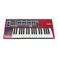
The Dynamic Control/Audio signal input(s). If you input an audio signal, the
color of the input(s) and logic signal output(s) change color to orange to indicate
that the module has adapted itself for audio rate bandwidth. Any input signal
changing from 0 units or below to anything above 0 units will be interpreted as a
‘high logic’ signal on the input(s). Any input signal changing from anything above 0 units to 0 units or
below will be interpreted as a ‘low logic’ signal on the input(s).
L
LL
L
O
OO
OG
GG
GI
II
IC
CC
C
S
SS
SI
II
IG
GG
GN
NN
NA
AA
AL
LL
L
O
OO
OU
UU
UT
TT
TP
PP
PU
UU
UT
TT
T
(
((
(
S
SS
S
)
))
)
The Dynamic Control/Audio signal (depending on input signal bandwidth) out-
put(s). Can output either a low logic signal (0 units) or a high logic signal (+64
units).
C
CC
C
L
LL
LO
OO
OC
CC
CK
KK
K
S
SS
SI
II
IG
GG
GN
NN
NA
AA
AL
LL
L
I
II
IN
NN
NP
PP
PU
UU
UT
TT
T
(
((
(
S
SS
S
)
))
)
The Dynamic Control/Audio clock signal input(s). A clock signal input with a single arrow
next to it will only react when an input signal changes from 0 units or below to anything above
0 units. A clock signal input with a double-arrow next to it will react when the input signal
crosses the 0 level in both directions (positive to negative and negative to positive).
R
RR
R
S
SS
ST
TT
T
I
II
IN
NN
NP
PP
PU
UU
UT
TT
T
The Dynamic Control/Audio Reset signal input is used to reset a module to its initial value.
The Reset signal input will only react when an input signal changes from 0 units or below to
anything above 0 units.
F
FF
F
U
UU
UN
NN
NC
CC
CT
TT
TI
II
IO
OO
ON
NN
N
D
DD
DR
RR
RO
OO
OP
PP
P
-
--
-
D
DD
DO
OO
OW
WW
WN
NN
N
S
SS
SE
EE
EL
LL
LE
EE
EC
CC
CT
TT
TO
OO
OR
RR
RS
SS
S
Click the Function drop-down selector to alter the processing function of the module. Note
that changing function with drop-down selectors will force the Sound engine to recalculate
and thus cause a brief moment of silence.
G
GG
G
A
AA
AT
TT
TE
EE
E
This module features two independent
logic gates. Each gate has two inputs and
one output and you select gate type from
the drop-down selectors. The gate types
are: AND, NAND, OR, NOR, XOR and XNOR. The respective gate functions are described with truth
tables when you click the drop-down selector. See also "Common Logic module parameters”.
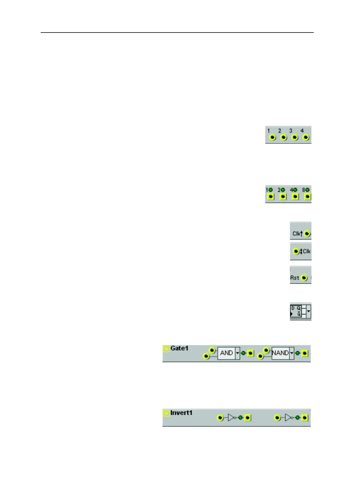
I
II
I
N
NN
NV
VV
VE
EE
ER
RR
RT
TT
T
The Invert module hold two independ-
ent logic inverters. When an incoming
signal is between >0 and +64 units, the