NORD MODULAR G2 V1.1 2. Overview: Nord Modular G2 rear panel
Page 17
act value is shown above in the corresponding A
SSIGNABLE
D
ISPLAY
. You can assign a maximum of 15
Columns (see below), each containing 8 parameters (in total 120 parameters) per Patch.
V
VV
V
A
AA
AR
RR
RI
II
IA
AA
AT
TT
TI
II
IO
OO
ON
NN
N
/M
/M/M
/M
O
OO
OR
RR
RP
PP
PH
HH
H
B
BB
BU
UU
UT
TT
TT
TT
TO
OO
ON
NN
NS
SS
S
There are 8 V
ARIATION
buttons with which you can select up to eight different Patch Variations (com-
plete parameter setups) within each Patch. In ‘Morph Mode’, these 8 buttons function as Morph group
selection buttons. They are used when you want to control several parameters in a Patch from a single
control source.
P
PP
P
A
AA
AT
TT
TC
CC
CH
HH
H
S
S S
S
E
EE
ET
TT
TT
TT
TI
II
IN
NN
NG
GG
G
This button is used when you want to switch display between the Patch parameters (which are printed
above the A
SSIGNABLE
D
ISPLAYS
) and the Programmable Parameter Pages.
P
PP
P
R
RR
RO
OO
OG
GG
GR
RR
RA
AA
AM
MM
MM
MM
MA
AA
AB
BB
BL
LL
LE
EE
E
P
P P
P
A
AA
AR
RR
RA
AA
AM
MM
ME
EE
ET
TT
TE
EE
ER
RR
R
P
P P
P
A
AA
AG
GG
GE
EE
ES
SS
S
B
BB
BU
UU
UT
TT
TT
TT
TO
OO
ON
NN
NS
SS
S
To the right are 5 main P
ARAMETER
P
AGE
buttons in combination with 3 C
OLUMN
buttons for a total
of 15 Columns per Patch. Each of these Columns can contain the 8 A
SSIGNABLE
K
NOBS
or B
UTTONS
for a total of 120 assignable parameters per Patch.
N
NN
N
O
OO
OR
RR
RD
DD
D
M
M M
M
O
OO
OD
DD
DU
UU
UL
LL
LA
AA
AR
RR
R
G2
G2 G2
G2
R
RR
RE
EE
EA
AA
AR
RR
R
P
PP
PA
AA
AN
NN
NE
EE
EL
LL
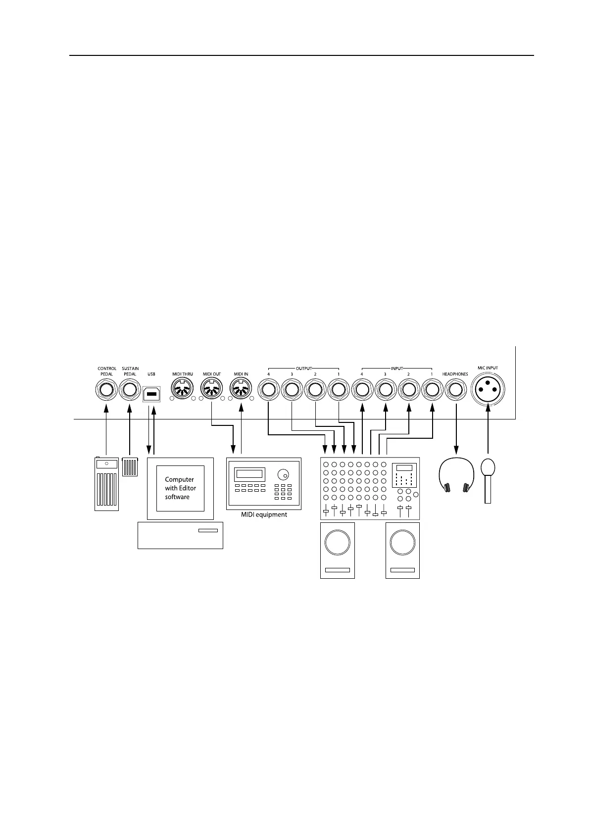
L
Connect a control/expression pedal to the C
ONTROL
P
EDAL
input. Connect a foot switch/sustain pedal
to the S
USTAIN
P
EDAL
input. The polarity of the input can be adjusted to suit different types of foot
switches.
Connect a free USB port of the computer that runs the Editor software to the USB Port.
Connect any external MIDI equipment to the M
IDI
I
N
, M
IDI
O
UT
and MIDI T
HRU
ports. This could
be a sequencer, a master keyboard or another MIDI device.