NORD MODULAR G2 V1.1 11. Module reference: Level group
Page 169
In the example above, algorithm 5 is used. If you look in the graph you can see that the output signals of
Operators 1, 3 and 5 are mixed to the DXRouter output. You can also see that Operator 2 is frequency
modulating Operator 1, Operator 4 is frequency modulating Operator 3 and Operator 6 is frequency
modulating Operator 5. Operator 6 also has an internal feedback loop as indicated by the orange line.
The internal feedback amount of Operator 6 in this algorithm can be set with the Feedback selector on
the DXRouter module.
L
LL
L
E
EE
EV
VV
VE
EE
EL
LL
L
G
GG
GR
RR
RO
OO
OU
UU
UP
PP
P
The Level group features modules for adding, subtracting, multiplying and modulating signal levels i the
Patch.
C
CC
C
O
OO
OM
MM
MM
MM
MO
OO
ON
NN
N
L
L L
L
E
EE
EV
VV
VE
EE
EL
LL
L
M
MM
MO
OO
OD
DD
DU
UU
UL
LL
LE
EE
E
P
PP
PA
AA
AR
RR
RA
AA
AM
MM
ME
EE
ET
TT
TE
EE
ER
RR
RS
SS
S
I
II
I
N
NN
NP
PP
PU
UU
UT
TT
T
(
((
(
S
SS
S
)
))
)
The Dynamic Control/Audio signal input(s) of the Level modules.
O
OO
O
U
UU
UT
TT
TP
PP
PU
UU
UT
TT
T
The Dynamic Control/Audio signal (depending on input signal type) output of the Level mod-
ules. Signal: Bipolar
B
BB
B
I
II
I
P/U
P/UP/U
P/U
N
NN
NI
II
I
B
BB
BU
UU
UT
TT
TT
TT
TO
OO
ON
NN
N
Click the Uni(polar) button to change the output signal from bipolar to unipolar. When you
switch to unipolar, the Level knob (see below) resolution is doubled.
L
LL
L
E
EE
EV
VV
VE
EE
EL
LL
L
K
KK
KN
NN
NO
OO
OB
BB
B
Set the modulation signal level. In unipolar mode (see above), the Level knob resolution
is doubled
C
CC
C
O
OO
ON
NN
NS
SS
ST
TT
TA
AA
AN
NN
NT
TT
T
The Constant Value module produces a
constant control signal at a selectable
offset level. See also "Common Level
module parameters”.
C
CC
C
O
OO
ON
NN
NS
SS
ST
TT
T
S
SS
S
W
WW
W
M
MM
M
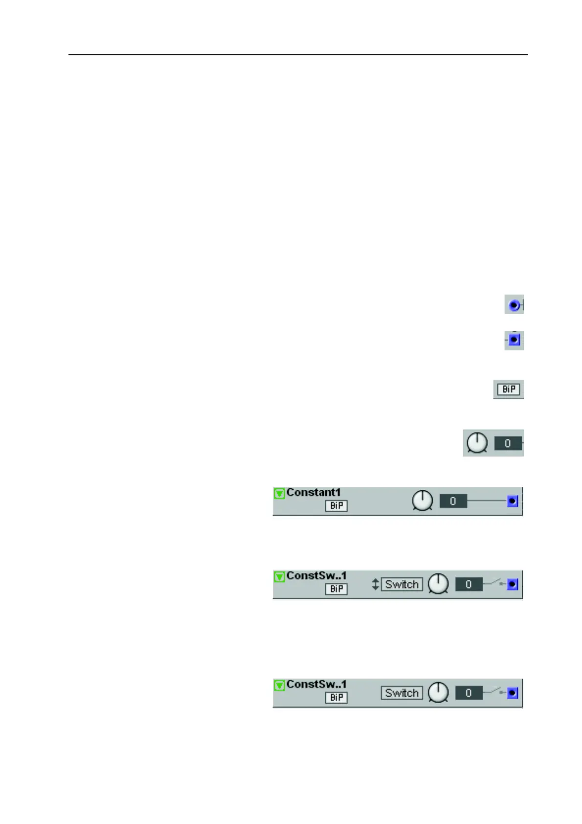
The Momentary Constant Switch mod-
ule produces a control signal at a selecta-
ble offset level when you click the Switch
button. Note that the Switch button is
momentary, i.e. clicking it will activate the output signal only for a short while. The Switch button can
also be renamed. See also "Common Level module parameters”.
C
CC
C
O
OO
ON
NN
NS
SS
ST
TT
T
S
SS
S
W
WW
W
T
TT
T
The Toggling Constant Switch module
produces a control signal at a selectable