NORD MODULAR G2 V1.1 11. Module reference: Filter group
Page 153
LP-F
LP-FLP-F
LP-F
I
II
IL
LL
LT
TT
TE
EE
ER
RR
R
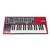
This is a non-resonant lowpass filter with
selectable slope (6/12/18/24/30/36 dB/
Oct.) and a modulation input for cut-off
frequency modulation. Note that chang-
ing slope will force the Sound Engine to recalculate and thus cause a brief moment of silence. See also
"Common Filter parameters”.
HP-F
HP-FHP-F
HP-F
I
II
IL
LL
LT
TT
TE
EE
ER
RR
R
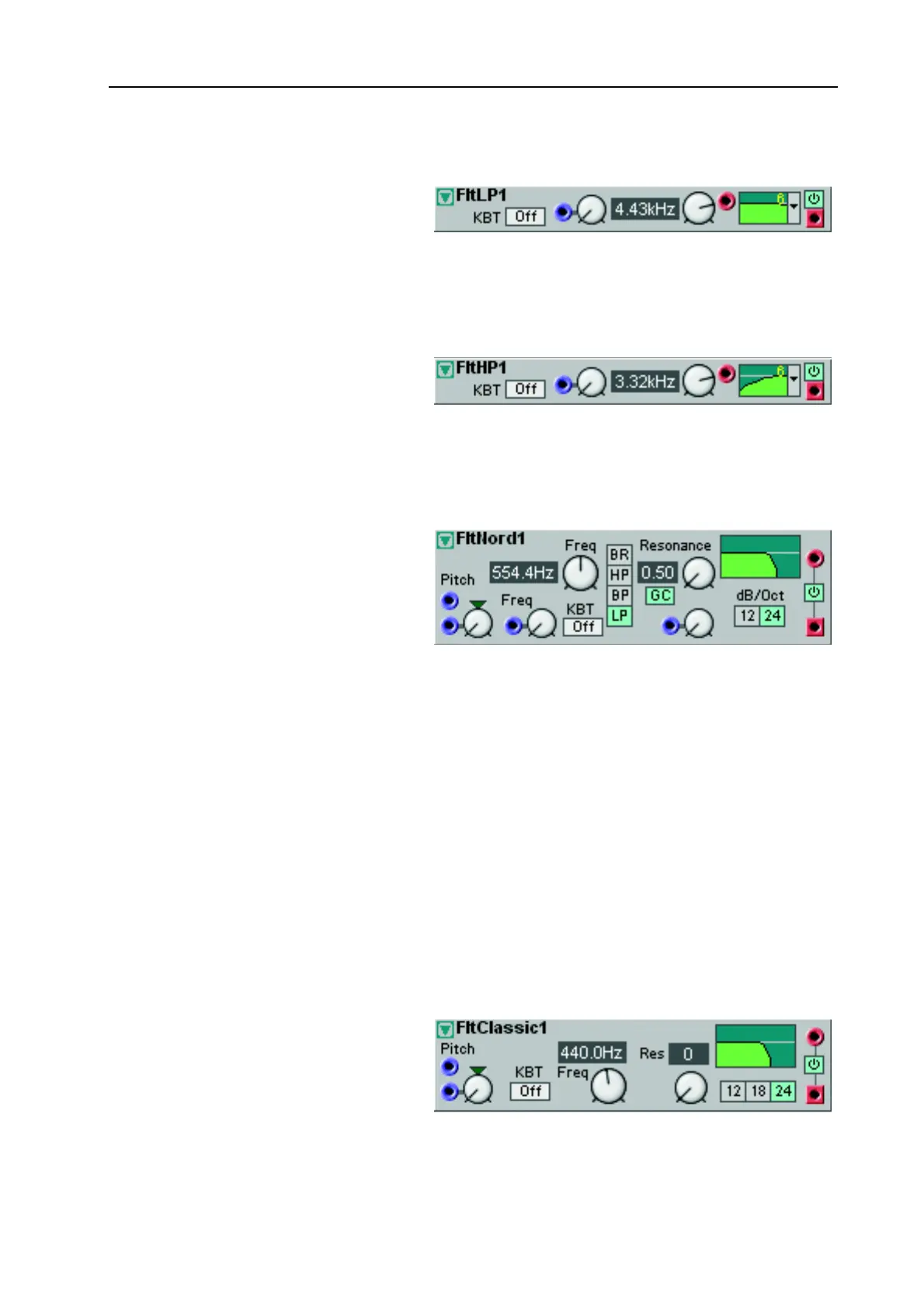
This is a non-resonant highpass filter
with selectable slope (6/12/18/24/30/36
dB/Oct.) and a modulation input for
cut-off frequency modulation. Note that
changing slope will force the Sound Engine to recalculate and thus cause a brief moment of silence.
See also "Common Filter parameters”.
F
FF
F
L
LL
LT
TT
T
N
NN
N
O
OO
OR
RR
RD
DD
D
This is a dynamic synthesizer filter with a
slope of either 12 or 24 dB/octave. It is a
multi-mode filter, providing a highpass,
a lowpass, a bandpass or a bandreject fil-
ter. The cut-off frequency and the reso-
nance can be modulated from external
sources.
F
FF
F
R
RR
RE
EE
EQ
QQ
Q
M
MM
MO
OO
OD
DD
DU
UU
UL
LL
LA
AA
AT
TT
TI
II
IO
OO
ON
NN
N
The blue Dynamic Control/Audio signal input for modulating the filter frequency from a control source.
The modulation amount is determined by the rotary knob next to the input of Attenuator Type III. See
“Frequency modulation (FM)” on page 34 for more info about frequency modulation.
F
FF
F
I
II
IL
LL
LT
TT
TE
EE
ER
RR
R
T
T T
T
Y
YY
YP
PP
PE
EE
E
S
SS
SE
EE
EL
LL
LE
EE
EC
CC
CT
TT
TO
OO
OR
RR
R
Select the filter type with the buttons. (This selector cannot be assigned to a Morph group). HP is a High-
pass filter, BP is a Bandpass filter and LP is a Lowpass filter. BR is a Band reject filter. When the BR filter
is selected, the Resonance knob will control the width of the frequency band to be rejected.
R
RR
R
E
EE
ES
SS
SO
OO
ON
NN
NA
AA
AN
NN
NC
CC
CE
EE
E
M
MM
MO
OO
OD
DD
DU
UU
UL
LL
LA
AA
AT
TT
TI
II
IO
OO
ON
NN
N
The blue Control signal input for modulating the resonance from a control source. The modulation
amount is determined by the rotary knob next to the input of Attenuator Type I. See also "Common
Filter parameters”.
F
FF
F
L
LL
LT
TT
T
C
CC
C
L
LL
LA
AA
AS
SS
SS
SS
SI
II
IC
CC
C
This is a lowpass filter which simulates
classic analog synthesizer filters. The
main difference between this filter and
other lowpass filters is the more narrow
resonance peak found in analog lowpass
filters. The slope is selectable between 12,