11. Module reference: FX group NORD MODULAR G2 V1.1
Page 190
left of the display box. Attenuate the modulation signal with the knob to the left of the display box [At-
tenuator Type I].
Q
QQ
Q
U
UU
UA
AA
AN
NN
NT
TT
TI
II
IZ
ZZ
ZA
AA
AT
TT
TI
II
IO
OO
ON
NN
N
(B
(B (B
(B
I
II
IT
TT
TS
SS
S
)
))
)
Select the bit resolution with the arrow buttons. Range: 1 to 12 bits and Off. ‘Off’ means full resolution,
i.e. 24 bits. The resolution is shown in the display box. See also "Common FX group parameters”.
F
FF
F
R
RR
RE
EE
EQ
QQ
Q
S
SS
S
H
HH
HI
II
IF
FF
FT
TT
T
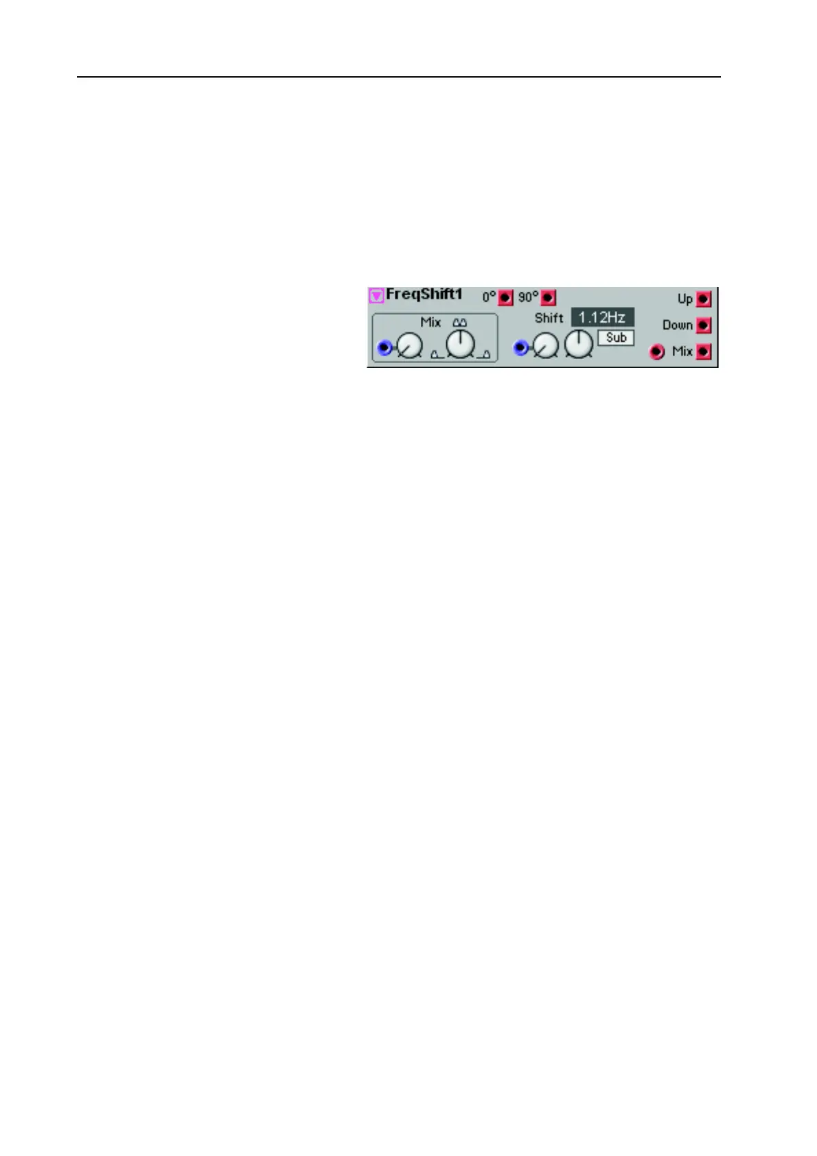
This is a Frequency Shifter. The module
takes an input audio signal and generates
a copy of all input signal partials. This
“copy” can then be frequency shifted in a
selectable number of Hz up or down.
Since the frequencies are shifted linearly
(as opposed to pitch shifting), the resulting signal will contain a lot of inharmonic frequencies. This is
great for creating far out “ring modulator” type of effects. The Frequency Shifter is also very useful for
adding “richness” to a sound. For example, adding just a slight amount of frequency shifting will make
the sound a lot richer.
S
SS
S
H
HH
HI
II
IF
FF
FT
TT
T
Set the amount of frequency shifting of the “copy” of the input signal with the Shift knob. The shifting
is linear frequency shifting as opposed to pitch shifting. A low Shift amount will give results similar to
pitch shifting whereas high Shift amounts will generate inharmonic signals. The Shift amount can be con-
trolled from an external source via the control signal input. The modulation amount can also be attenu-
ated [Attenuator Type I].
H
HH
H
I
II
I
/L
/L/L
/L
O
OO
O
/S
/S/S
/S
U
UU
UB
BB
B
S
SS
SC
CC
CR
RR
RO
OO
OL
LL
LL
LL
L
B
BB
BU
UU
UT
TT
TT
TT
TO
OO
ON
NN
NS
SS
S
Select range for the frequency shifting of the input signal copy.
M
MM
M
I
II
IX
XX
X
With the Mix knob you determine which part of the input signal copy to output through the Mix output
(see below). Range: from only frequencies below the input signal pitch to only frequencies above the in-
put signal pitch. The Mix can be controlled from an external source via the control signal input. The
modulation amount can also be attenuated [Attenuator Type I].
0
0 0
0
D
DD
DE
EE
EG
GG
GR
RR
RE
EE
EE
EE
E
O
OO
OU
UU
UT
TT
TP
PP
PU
UU
UT
TT
T
The output of the unaffected input signal. Like a bypass, if you like. Signal: Bipolar
90
90 90
90
D
DD
DE
EE
EG
GG
GR
RR
RE
EE
EE
EE
ES
SS
S
O
OO
OU
UU
UT
TT
TP
PP
PU
UU
UT
TT
T
The output of the input signal, phase shifted 90 degrees. Signal: Bipolar
U
UU
U
P
PP
P
O
OO
OU
UU
UT
TT
TP
PP
PU
UU
UT
TT
T
The output of the upper frequency shifted band. Signal: Bipolar
D
DD
D
O
OO
OW
WW
WN
NN
N
O
OO
OU
UU
UT
TT
TP
PP
PU
UU
UT
TT
T
The output of the lower frequency shifted band. Signal: Bipolar
M
MM
M
I
II
IX
XX
X
O
OO
OU
UU
UT
TT
TP
PP
PU
UU
UT
TT
T
The output of the mix of the input signal and the frequency shifted signal. Signal: Bipolar. See also
"Common FX group parameters”.