11. Module reference: Switch group NORD MODULAR G2 V1.1
Page 168
ple&Hold module. As soon as a signal at the leftmost input is shifting from 0 units or below to anything
above 0 units, the switch closes and the input signal is routed to the output. When the signal at the left-
most input switches to 0 units or below, the module transmits the value of the latest input sample to the
output. See also "Common Switch parameters”.
DXR
DXRDXR
DXR
O
OO
OU
UU
UT
TT
TE
EE
ER
RR
R
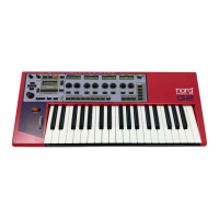
The DXRouter module is intended for
use with the Operator modules de-
scribed on page 134. It works exactly
like the Algorithm selector on the DX7
synthesizer, i.e. it routes the Operator
output signals either to Operator FM in-
puts or to the audio mix output and al-
lows for different types of FM synthesis.
F
FF
F
E
EE
EE
EE
ED
DD
DB
BB
BA
AA
AC
CC
CK
KK
K
Select the internal feedback amount for the connected Operator. An internal feedback loop is indicated
with orange lines in the DXRouter graph. Range 0-7.
A
AA
A
L
LL
LG
GG
GO
OO
OR
RR
RI
II
IT
TT
TH
HH
HM
MM
M
Select one of 32 different algorithms (connection paths) for the connected Operator modules. These 32
algorithms corresponds to the factory algorithms of the DX7 synthesizer. The algorithms are shown in
the graph.
E
EE
E
X
XX
XA
AA
AM
MM
MP
PP
PL
LL
LE
EE
E
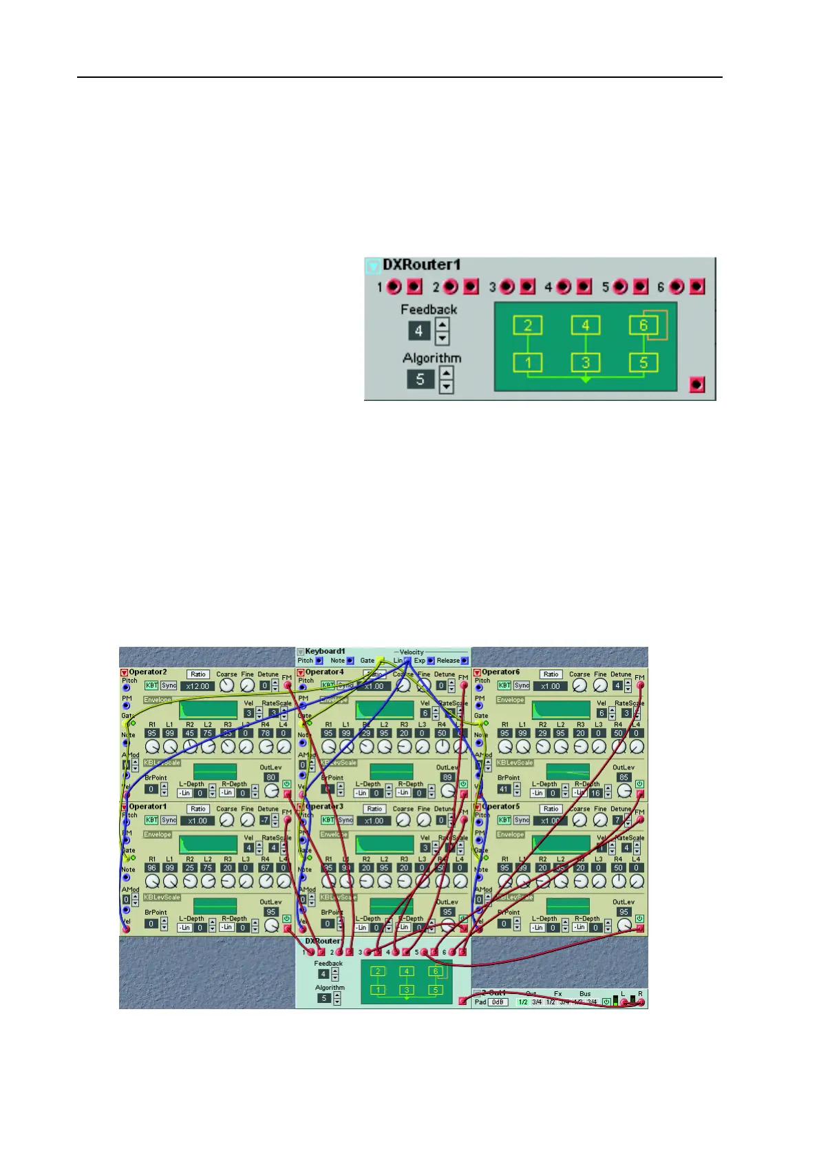
Below is an example of the DXRouter module used together with six Operator modules to form a basic
DX7 configuration. Connect each Operator output to the corresponding input of the DXRouter mod-
ule. Connect each output of the DXRouter module to the corresponding FM input of each Operator.