11. Module reference: Logic group NORD MODULAR G2 V1.1
Page 178
output transmits a low logic signal (0 units). When an incoming signal is between 0 and -64 units it trans-
mits a logic high signal (+64 units). See also "Common Logic module parameters”.
F
FF
F
L
LL
LI
II
IP
PP
P
F
FF
F
L
LL
LO
OO
OP
PP
P
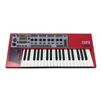
The FlipFlop module can be described
as a “logic switch with memory func-
tion”
The module can perform
two different types of flip-
flop techniques: the ‘Set-
Reset’ and the ‘D-Type
with Reset’. To describe the
respective functions of
these flip-flops, let’s have a
look at the diagrams to the
right. See also "Common
Logic module parameters”.
C
CC
C
L
LL
LK
KK
K
D
DD
D
I
II
IV
VV
V
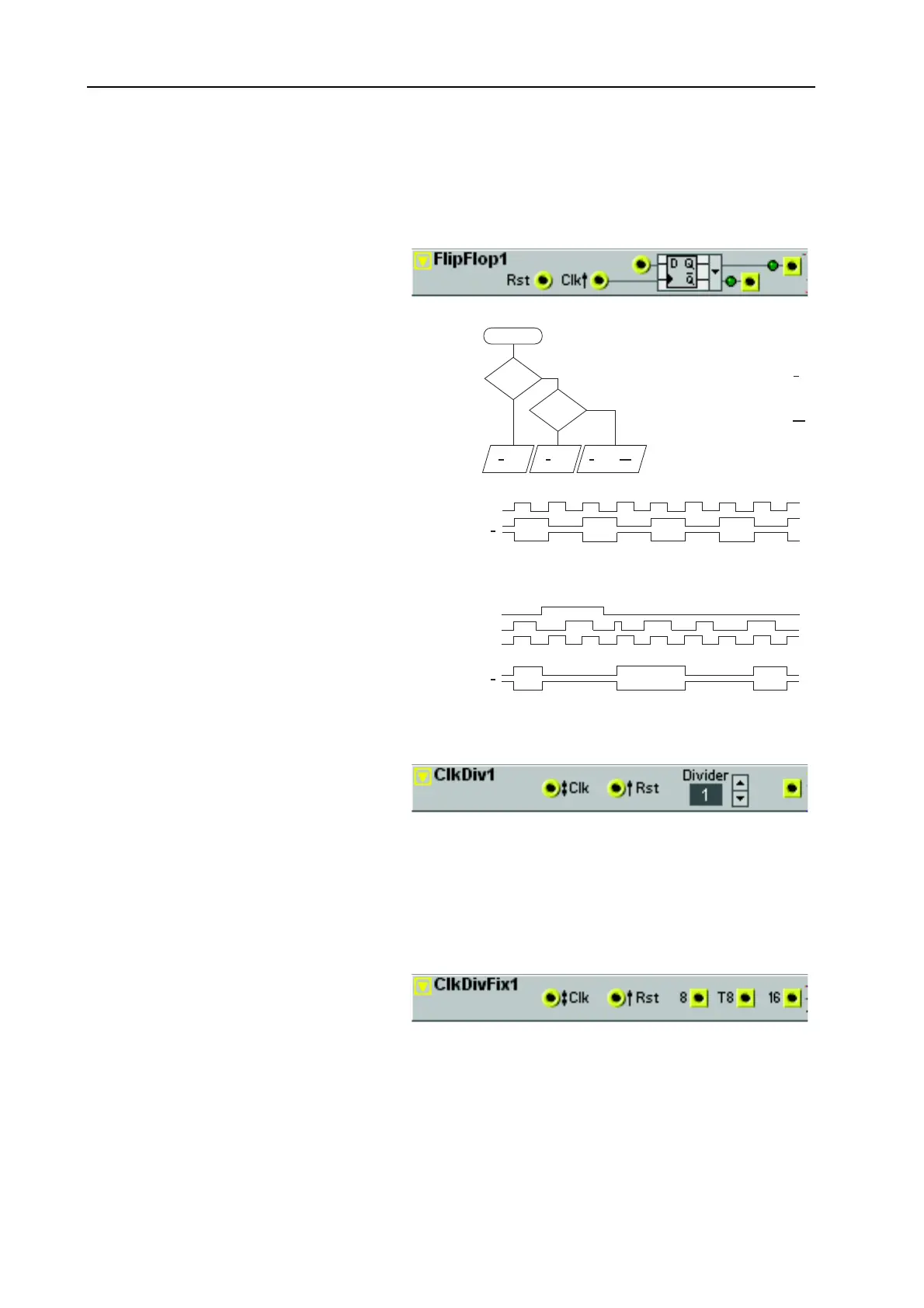
The Clock Divider module can be used
for dividing incoming clock pulses (or
zero-crossings) by a factor set by you.
The module transmits a high logic pulse
after it has received a user-defined number of zero-crossing transitions.
D
DD
D
I
II
IV
VV
VI
II
ID
DD
DE
EE
ER
RR
R
Set the desired division with the buttons. Range: 1 to 128. The denumerator is shown in the Display box.
C
CC
C
L
LL
LK
KK
K
D
DD
D
I
II
IV
VV
V
F
FF
F
I
II
IX
XX
X
The Fixed Clock Divider module di-
vides an incoming clock signal (or bipo-
lar signal) to three fixed resulting signals.
This provides you with an easy way of
extracting 8 note, 8 note-triplets and 16th note clock pulses from a clock signal, for example.
8, T8 & 16
8, T8 & 168, T8 & 16
8, T8 & 16
The outputs where, for example, 24 incoming pulses are divided to 2, 3 and 4 pulses respectively. Signal:
Logic. See also "Common Logic module parameters”.
Rst=1?
Q=0
Q=1
Q=1
Q=0
Q=Clk Tgl
Q=Clk Tgl
S=1?
No
Yes
Yes
No
Start
Clk
Q
Q
Input Output
Rst S Clk Q Q
1 X X 0 1
0 1 X 1 0
0 0 Tgl Tgl Tgl
Rst
D
Clk
Q
Q
The Set-Reset flip-flop
works according to the
flow-chart and table to
the right. The ‘X’ in the
table means it doesn’t
matter if the value is ‘0’
or ‘1’.
A toggling signal (Tgl)
alternates between ‘0’
and ‘1’ on the positive
edge of every full Clock
period.
The D-type flip-flop
outputs what’s current-
ly on the D input on the
positive edge of each
Clk pulse - if Rst is ‘0’
(see the time diagram
to the right).