NORD MODULAR G2 V1.1 11. Module reference: Envelope group
Page 145
O
OO
O
U
UU
UT
TT
TP
PP
PU
UU
UT
TT
T
T
T T
T
Y
YY
YP
PP
PE
EE
E
S
SS
SC
CC
CR
RR
RO
OO
OL
LL
LL
LL
L
B
BB
BU
UU
UT
TT
TT
TT
TO
OO
ON
NN
N
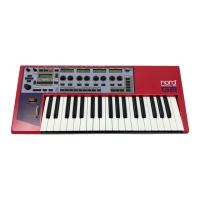
With the Output Type scroll button you determine how the envelope control signal should be
output and affect the envelope controlled amplifter. There are six different alternatives:
• Pos: Positive Unipolar signal starting from 0 units, going up to +64
units and then down to 0 units again.
• PosInv: Positive Unipolar signal starting from +64 units, going
down to 0 units and then up to +64 units again, i.e. an inverted sig-
nal.
• Neg: Negative Unipolar signal starting from -64 units, going up to 0
units and then down to -64 units again.
• NegInv: Negative Unipolar signal starting from 0 units, going down
to -64 units and then up to 0 units again.
• Bip: Bipolar signal with a range of 64 units and its sustain level at 0
(the MultiEnv can have user definable sustain level in this mode).
• BipInv: Bipolar inverted signal with a range of 64 units and its sus-
tain level at 0 (the MultiEnv can have user definable sustain level in
this mode).
Note! The Multi-Envelope module has full range (-64 to 64 units) in Bipolar and Inverted Bipolar
mode.
I
II
IN
NN
NP
PP
PU
UU
UT
TT
T
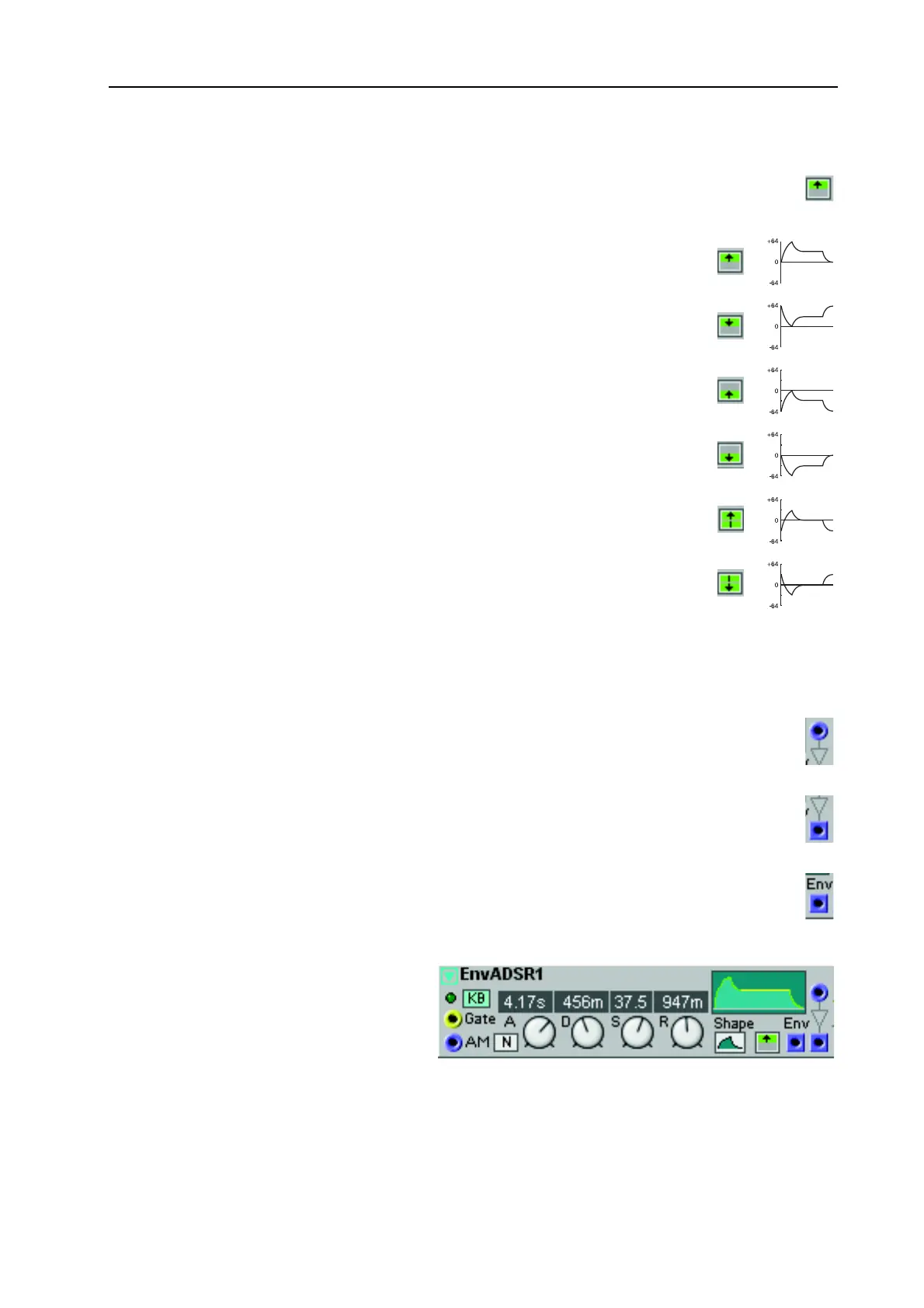
The Dynamic Control/Audio signal input. Here you can patch a bipolar signal to the envelope
controlled amplifter.
O
OO
O
U
UU
UT
TT
TP
PP
PU
UU
UT
TT
T
The Dynamic Control/Audio signal output from the envelope controlled amplifter.
Signal: Bipolar.
E
EE
E
N
NN
NV
VV
V
O
OO
OU
UU
UT
TT
TP
PP
PU
UU
UT
TT
T
The blue control signal output from the envelope generator.
Signal: Unipolar or Bipolar.
ADSR-E
ADSR-EADSR-E
ADSR-E
N
NN
NV
VV
V
This is a regular four-stage ADSR (At-
tack, Decay, Sustain and Release) enve-
lope. The ADSR Envelope is well suited
for controlling audio signal amplitude,
pitch and filter cut-off frequency, for ex-
ample. See also "Common Envelope
Generator parameters”.
Pos:
PosInv:
Neg:
NegInv:
Bip:
BipInv: