6. Patches: Patches (in-depth) NORD MODULAR G2 V1.1
Page 42
C
CC
C
O
OO
OL
LL
LO
OO
OR
RR
RI
II
IN
NN
NG
GG
G
A
AA
A
M
MM
MO
OO
OD
DD
DU
UU
UL
LL
LE
EE
E
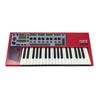
To distinguish a module, or a group of modules, from other
modules in a Patch, it’s possible to apply a color to the module.
Select a color from the Color selector in the Toolbar. Any new
modules you add to the Patch window will now get the selected color. You can also focus any modules
in the Patch window by Shift-clicking them and then clicking on the “paint bucket” icon to apply the
selected color to the module(s) or select another color from the drop-down palette.
C
CC
C
O
OO
ON
NN
NN
NN
NE
EE
EC
CC
CT
TT
TI
II
IN
NN
NG
GG
G
M
MM
MO
OO
OD
DD
DU
UU
UL
LL
LE
EE
ES
SS
S
I
II
I
N
NN
NP
PP
PU
UU
UT
TT
TS
SS
S
A
AA
AN
NN
ND
DD
D
O
OO
OU
UU
UT
TT
TP
PP
PU
UU
UT
TT
TS
SS
S
There are two types of main connectors on the modules in the Nord Modular G2 Editor: inputs and out-
puts. The inputs are circular and the outputs are square.
C
CC
CO
OO
ON
NN
NN
NN
NE
EE
EC
CC
CT
TT
TO
OO
OR
RR
R
T
TT
TY
YY
YP
PP
PE
EE
ES
SS
S
There are three different types of connectors that are used for different signals. These connectors are dis-
tinguished by different colors:
• audio signal connectors: Red (24 bit and 96 kHz sampling frequency)
• control signal connectors: Blue (24 bit and24 kHz sampling frequency)
• logic signal connectors. Yellow (24 bit and 24 kHz sampling frequency) or Orange (24 bit and 96 kHz
sampling frequency)
C
CC
C
O
OO
ON
NN
NN
NN
NE
EE
EC
CC
CT
TT
TI
II
IN
NN
NG
GG
G
C
CC
CA
AA
AB
BB
BL
LL
LE
EE
ES
SS
S
I
II
IN
NN
N
A
AA
A
P
P P
P
A
AA
AT
TT
TC
CC
CH
HH
H
Place the cursor on a module connector and click-hold. The cursor will change to a plug.
Drag the cursor to a suitable connection elsewhere in the Patch. As you drag the cursor away
from the source connector, a line will appear between the cursor and the connector. When
you reach the destination connector, the cursor will change to a cable with a white dot instead
of a plug. As you release the mouse button, a cable will appear between the two connections. The color
of the output connection will determine the color of the resulting cable. You can later change the cable
color if you like.
It is also possible to connect cables between connectors of different colors, e.g. connect an audio signal
output to a control signal input etc. This depends on the actual application. If a connection is not possible
to make, this will be shown; the cursor will not change to a cable with a dot as you reach the “illegal”
destination connector. It is not possible to damage the system in any way by connecting “wrong” - feel
free to experiment!
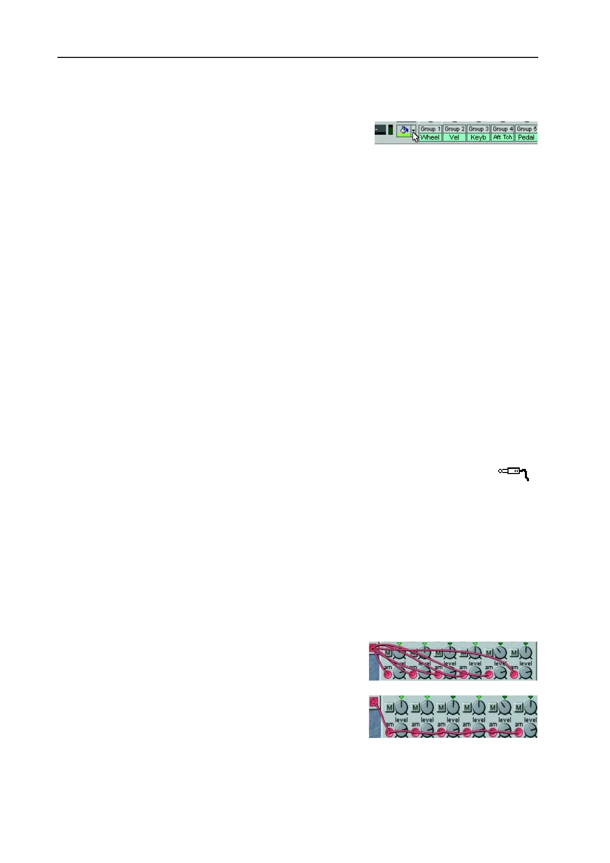
You can connect one output to several inputs to make a parallel
connection.
You can also make a serial connection, from input to input. The
result is exactly the same as in a branch connection. If a module
within a serial cable chain is removed, the remains of the cable
chain will be re-routed.