NORD MODULAR G2 V1.1 11. Module reference: In/Out group
Page 111
O
OO
O
N
NN
N
/O
/O/O
/O
F
FF
FF
FF
F
Click the On/Off button to mute the signal(s) of the In/Out module. Blue color indicates ‘On’
and gray ‘Mute’
L
LL
L
E
EE
EV
VV
VE
EE
EL
LL
L
M
MM
ME
EE
ET
TT
TE
EE
ER
RR
RS
SS
S
The level meters on the Input modules displays the following signal levels: green LEDs
between -40dB and 0dB, yellow LEDs between >0dB and +11dB and red LED at >11dB.
2-O
2-O2-O
2-O
U
UU
UT
TT
T
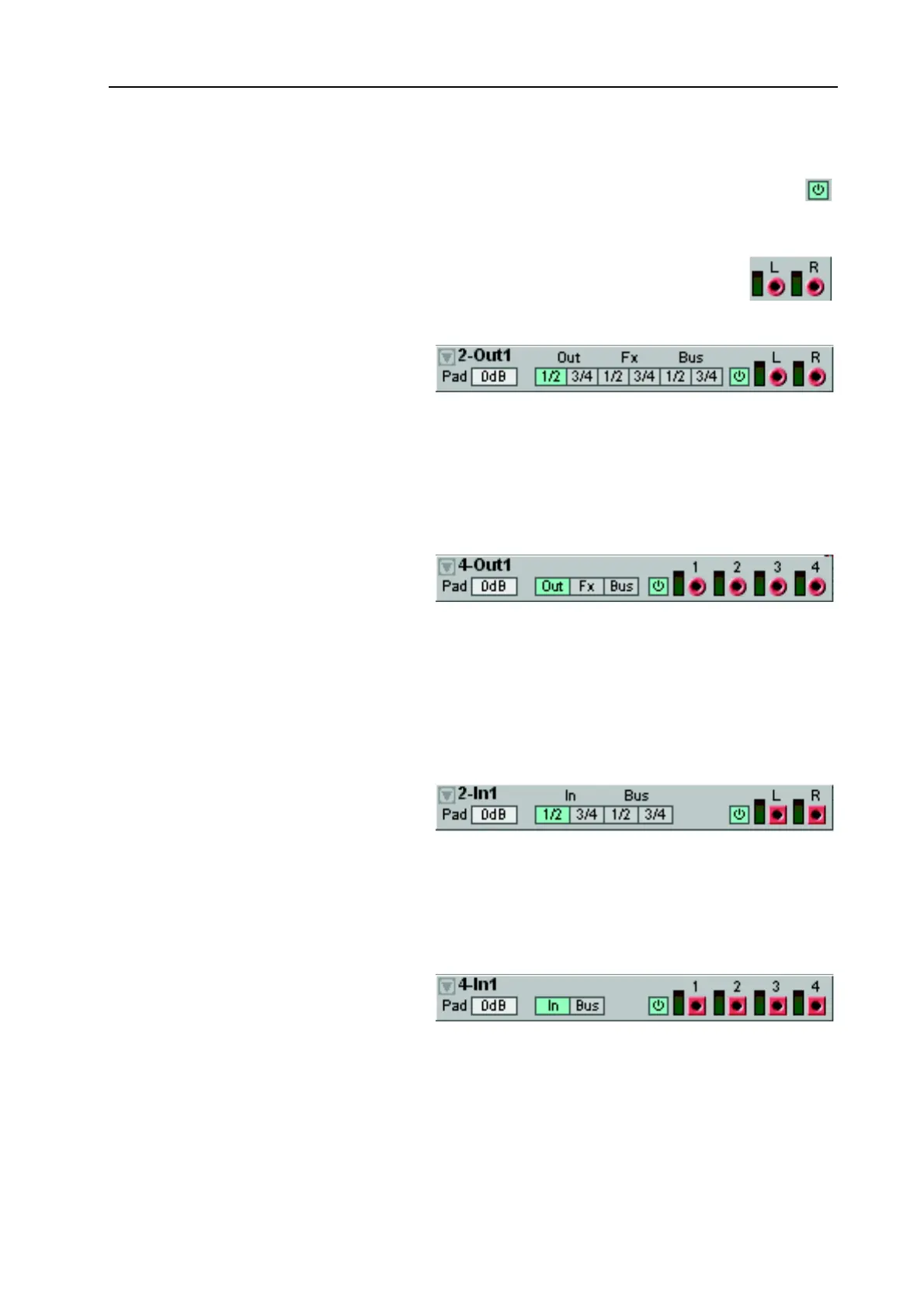
This module can be used to patch stereo
signals to the Audio Outs, the FX Area or
the audio Buses.
S
SS
S
O
OO
OU
UU
UR
RR
RC
CC
CE
EE
E
S
SS
SE
EE
EL
LL
LE
EE
EC
CC
CT
TT
TO
OO
OR
RR
R
B
BB
BU
UU
UT
TT
TT
TT
TO
OO
ON
NN
NS
SS
S
Here you select the signal destination: Audio Out channels 1/2 or 3/4, FX Area channels 1/2 or 3/4 or
audio Bus channels 1/2 or 3/4. Note that you cannot use the FX channels when the module is placed
in the FX Area. See also "Common In/Out module parameters and definitions”.
4
44
4-O
-O-O
-O
U
UU
UT
TT
T
This module can be used to patch individ-
ual signals to different destinations: the
Audio Out, the FX Area or the Global
Buses.
S
SS
S
O
OO
OU
UU
UR
RR
RC
CC
CE
EE
E
S
SS
SE
EE
EL
LL
LE
EE
EC
CC
CT
TT
TO
OO
OR
RR
R
B
BB
BU
UU
UT
TT
TT
TT
TO
OO
ON
NN
NS
SS
S
Here you select the signal destination: Audio Out channels 1-4, FX Area channels 1-4 or audio Bus chan-
nels 1-4. Note that you cannot use the FX channels when the module is placed in the FX Area. See also
"Common In/Out module parameters and definitions”.
2
22
2-I
-I-I
-I
N
NN
N
This module can be used to route stereo
signals from the Audio Ins or the audio
Buses.
S
SS
S
O
OO
OU
UU
UR
RR
RC
CC
CE
EE
E
S
SS
SE
EE
EL
LL
LE
EE
EC
CC
CT
TT
TO
OO
OR
RR
R
B
BB
BU
UU
UT
TT
TT
TT
TO
OO
ON
NN
NS
SS
S
Here you select the signal source: Audio In channels 1/2 or 3/4 or audio Bus channels 1/2 or 3/4. See also
"Common In/Out module parameters and definitions”.
4
44
4-I
-I-I
-I
N
NN
N
This module can be used to route individ-
ual signals from the Audio Ins or the au-
dio Buses.
S
SS
S
O
OO
OU
UU
UR
RR
RC
CC
CE
EE
E
S
SS
SE
EE
EL
LL
LE
EE
EC
CC
CT
TT
TO
OO
OR
RR
R
B
BB
BU
UU
UT
TT
TT
TT
TO
OO
ON
NN
NS
SS
S
Here you select the signal source: Audio In channels 1-4 or audio Bus channels 1-4. See also "Common
In/Out module parameters and definitions”.