5. Basic functions: Modulation NORD MODULAR G2 V1.1
Page 32
M
MM
M
O
OO
OD
DD
DU
UU
UL
LL
LA
AA
AT
TT
TI
II
IO
OO
ON
NN
N
The method of controlling one function in a module with another function is called to “modulate”.
When you play on a keyboard and the oscillator changes its pitch, you are modulating the pitch with the
keyboard signal. Another example is an envelope opening up a filter when a key is pressed. Logic signals
from the keys tell the envelope to start modulating the cut-off frequency of the filter. Modulation can be
positive or negative, e.g. the cut-off frequency of a filter can increase with positive modulation and de-
crease with negative modulation or vice versa. As you will see, there are some modules in Nord Modular
G2 that can change the polarity of a modulator signal. Some modules can be set to send either bipolar or
unipolar control signals, like the Constant module or the Control Sequencer module.
M
MM
M
O
OO
OD
DD
DU
UU
UL
LL
LA
AA
AT
TT
TI
II
IO
OO
ON
NN
N
I
II
IN
NN
NP
PP
PU
UU
UT
TT
TS
SS
S
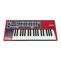
A module parameter that can be modulated from an external
source has a modulation input, often in combination with mod-
ulation amount control. This is called a mod-input. The modula-
tion amount control attenuates the incoming signal. The mod-
inputs can be red, like the Sync, FM and Shape inputs of the Os-
cillatorB module, which means they are capable of handling sig-
nals at full audio bandwidth, or they can be blue, like the Vowel
modulation input of the Voice Filter module, working at 1/4 au-
dio bandwidth. The modulation inputs can also be self-optimiz-
ing, like the Pitch inputs of the Oscillator B module, meaning that they adapt their bandwidth to the
incoming modulation signal bandwidth. This is indicated by the inputs changing color.
M
MM
M
O
OO
OD
DD
D
-
--
-
A
AA
AM
MM
MO
OO
OU
UU
UN
NN
NT
TT
T
K
KK
KN
NN
NO
OO
OB
BB
BS
SS
S
(
( (
(
A
AA
AT
TT
TT
TT
TE
EE
EN
NN
NU
UU
UA
AA
AT
TT
TO
OO
OR
RR
RS
SS
S
)
))
)
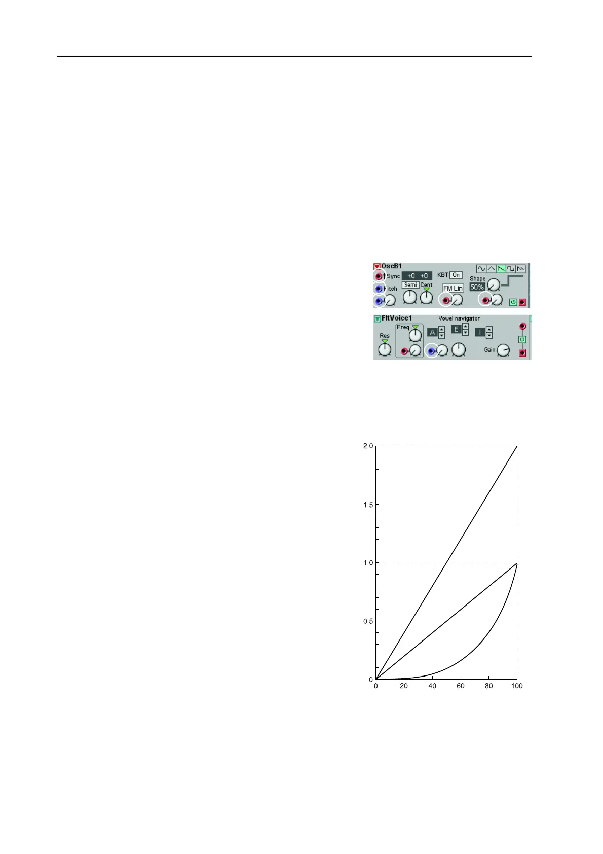
There are four different response behav-
iors of the mod-amount knobs next to
the modulation inputs: linear [Type I],
exponential/dB [Type II] and amplified
linear [Type III]. The different response
type(s) will be indicated for each module
in the module reference section starting
on page 109.
[T
[T[T
[T
Y
YY
YP
PP
PE
EE
E
I]
I] I]
I]
The mod-amount knobs attenuates the
incoming signal in a linear fashion. A set-
ting of 100 (maximum) leaves the in-
coming signal unaffected, a setting of 50
attenuates the incoming signal by a factor
0.5 (leaving half of the level of the in-
coming signal to modulate). A setting of
0 shuts off the modulation completely.
Oscillator pulse width modulation is an
example of Type I attenuation.
[T
[T[T
[T
Y
YY
YP
PP
PE
EE
E
II]
II] II]
II]
The mod-amount knob attenuates the incoming signal in an exponential fashion. A setting of 100 (max-
imum) leaves the incoming signal unaffected, a setting of 50 attenuates the incoming signal by a factor
Mod-amount setting
Signal attenuation/
amplification factor
TYPE I
TYPE II
TYPE III