+RZ WR 2
HUDWH WKH &RQWURO 3DQHO
How to Operate the Control Panel with an Output Circuit Trouble
32 AFC-600 Operations PN 51033:A 3/8/99
+RZWR2SHUDWHWKH&RQWURO3DQHOZLWKDQ2XWSXW&LUFXLW7URXEOH
2YHUYLHZRI2XW
XW&LUFXLWV
Output circuits include NACs, Panel Circuits 1-64, control/relay modules, and
transponder points. This section contains a description of control panel operation for
each type of output circuit.
• NACs include the four bell circuits (TB7-TB10 on the MPS-6)
• Panel circuits include ICM-4, CRM-4, VCM-4 or DCM-4 panel modules
connected to J1 or J2 on the control panel
• Control/relay modules include control/relay modules connected to the control
panel on an SLC
• Transponder points include XPC (CLIP only) or XP5-C (CLIP or Flash-Scan).
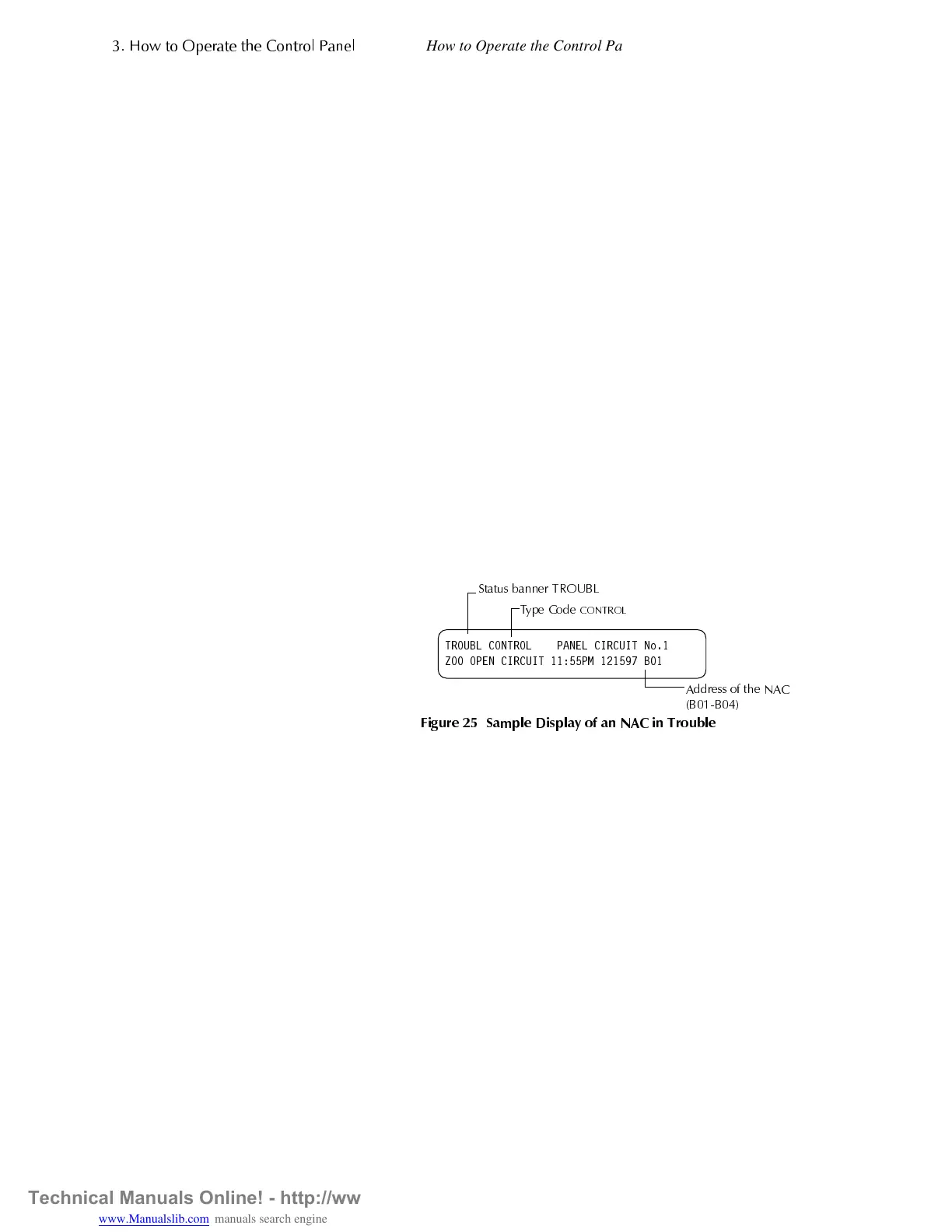
+RZWKH&RQWURO3DQHO,QGLFDWHVDQ1$&7URXEOH
Activation of an NAC causes the control panel to do the following:
• Flash the
SYSTEM
TROUBLE
LED
• Turn on the Trouble relay (MPS-6, TB5)
• Send a message to the LCD display, History buffer, and installed printers, terminal
mode LCD-80s, and CRT-2s
• Display a
TROUBL
status banner and a
CONTROL
Type Code on the LCD display,
along with information specific to the device, as shown in Figure 25.
)LJXUH 6DPSOH 'LVSOD\ RI DQ 1$& LQ 7URXEOH
Continued on the next page...
7528%/ &21752/ 3$1(/ &,5&8,7 1R
= 23(1 &,5&8,7 30 %
6WDWXV EDQQHU 7528%/
7
H &RGH
&21752/
$GGUHVV RI WKH 1$&
%%
Technical Manuals Online! - http://www.tech-man.com