9RLFH $ODUP 6
VWHPV
Audio Amplifiers
68 AFC-600 Operations PN 51033:A 3/8/99
+RZWR$G
XVWWKH$XGLR*DLQ/HYHOIRUDQ$XGLR$P
OLILHU
An audio amplifier contains a multi-position rotary switch that lets you adjust the gain
of the audio output signal. This adjustment compensates for audio line losses. After
correct adjustment, an audio amplifier can produce its maximum rated output power of
25 Vrms (AA-30, AA-120) or 70.7 Vrms (AA-100). Refer to Figure 70 on page 66
(AA-30) or Figure 71 on page 67 (AA-100 and AA-120) for the location of the Audio
Gain Rotary Switch.
When finished installing all amplifiers and associated circuitry, adjust the audio gain.
To so by using a small slotted screwdriver to turn the Audio Gain Rotary Switch until
the
NORMAL
LEVEL
LED and
INCORRECT
LEVEL
LED are properly adjusted as shown in
Table 33:
7DEOH $G
XVWLQ
WKH $XGLR /HYHO
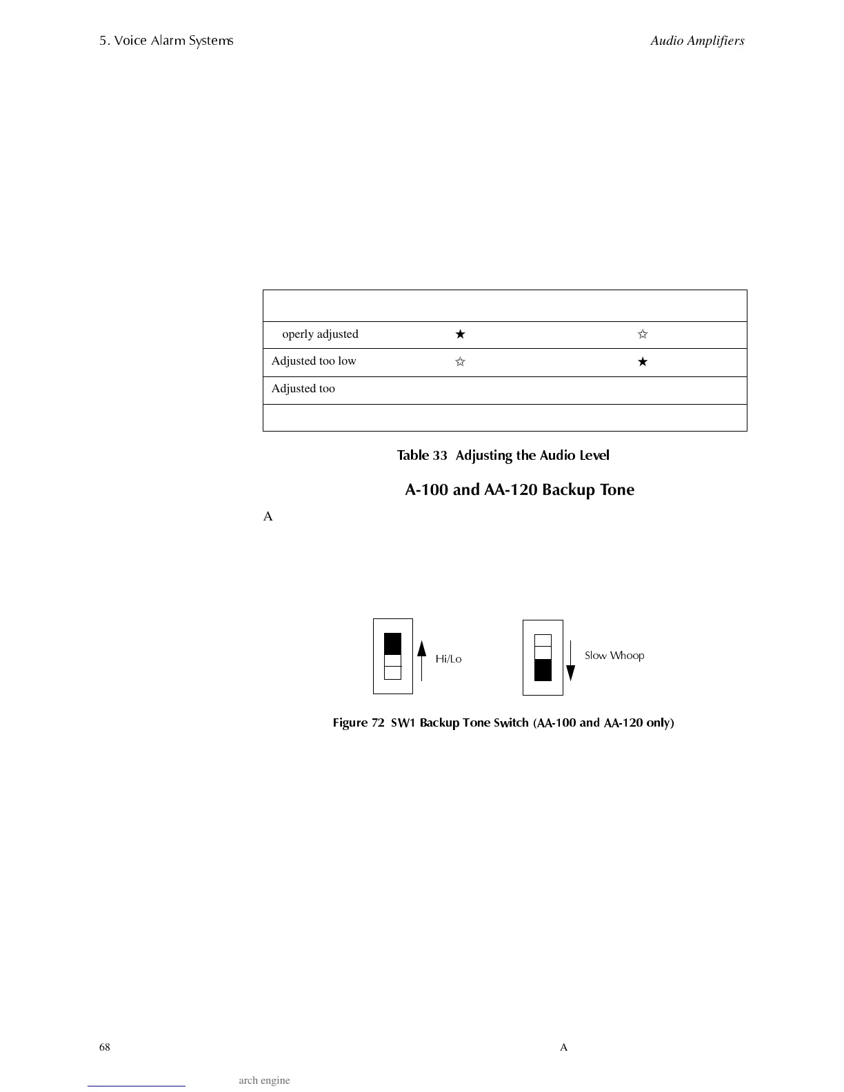
+RZWR6HOHFWWKH$$DQG$$%DFNX
7RQH
An audio amplifier automatically produces a backup tone when the low-level audio
input is lost. You can select the backup tone by following these steps.
1. Locate SW1 in the lower right-hand corner of the AA-100 or AA-120 circuit board
(See Figure 71 on page 67).
2. Set SW1 to Hi/Lo or Slow Whoop as the default backup tone (Figure 72).
)LJXUH 6: %DFNXS 7RQH 6ZLWFK $$ DQG $$ RQO\
Audio Level Normal Level LED Incorrect Level LED
Properly adjusted
★✩
Adjusted too low
✩★
Adjusted too high
★★
★
LED on
✩
LED off
+L/R
6ORZ :KRR
Technical Manuals Online! - http://www.tech-man.com