5HDG 6WDWXV 2
HUDWLRQ
How to View and Print Read Status Information
40 AFC-600 Operations PN 51033:A 3/8/99
+RZ WR 9LHZ 5HDG 6WDWXV
IRU D 'HWHFWRU
From the Read Status screen, press
0
, then press the
ENTER
key. You can now view
Read Status for a detector as follows: press
DETECTOR
, enter the SLC number followed
by the three digit address, then press the
ENTER
key. For example, to read the status of
detector D203: press
DETECTOR
, enter the SLC number, enter 203, then press the
ENTER
key. The control panel displays information about the detector as shown in Figure 34:
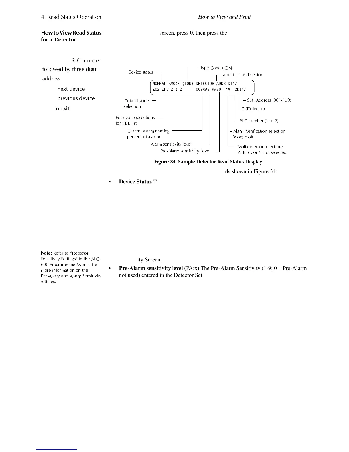
)LJXUH 6DPSOH 'HWHFWRU 5HDG 6WDWXV 'LVSOD\
The following notes contain descriptions of the fields shown in Figure 34:
•
Device Status
The status of the detector: Normal, Alarm, or Test.
•
Type Code
The software Type Code that identifies the type of detector. (Refer to
“Point Programming” in AFC-600 Programming Manual.)
•
Default Zone Selection
Zone 01 (Heat detectors) Zone 02 (Ion detectors) Zone 03
(Photo detectors) Zone 04 (Laser detectors) Zone 05 (Multisensor).
• CBE list
Four additional zones that along with the default zone make up the CBE
list for the device.
•
Current alarm reading
(xxx%) The current alarm reading of the detector, as a
percentage of the alarm sensitivity setting.
1RWH
5HIHU WR ´'HWHFWRU
6HQVLWLYLW
6HWWLQ
Vµ LQ WKH $)&
3UR
UDPPLQ
0DQXDO IRU
PRUH LQIRUPDWLRQ RQ WKH
3UH$ODUP DQG $ODUP 6HQVLWLYLW
VHWWLQ
V
•
Alarm sensitivity level
(Ax) The alarm sensitivity (x=1-9) entered in the Detector
Sensitivity Screen.
•
Pre-Alarm sensitivity level
(PA:x) The Pre-Alarm Sensitivity (1-9; 0 = Pre-Alarm
not used) entered in the Detector Settings Screen.
•
Cooperative Multi-Detector selection
A smoke detector programmed to evaluate
readings from nearby detectors in making Alarm or Pre-Alarm decisions.
Cooperative Multi-Detector sensing also allows the combination of ionization with
photoelectric technology in reaching an alarm decision.
*
– Multi-not used.
A
– combines the detector’s alarm decision with the next SLC address above.
B
– combines the detector’s alarm decision with the next SLC address below.
C
– combines the detector’s alarm decision with the next SLC address above and
the next SLC address below.
•
Alarm Verification
(* or V)
* – Alarm Verification not programmed for this detector.
V – Alarm Verification enabled.
Alarm Verification
is a user-defined global time function that can reduce the
number of nuisance alarms. Refer to the glossary for a definition.
•
Device SLC Address
The SLC address of the detector.
&
&+
6/& QXPEHU
IROORZHG E
WKUHH GL
LW
DGGUHVV
&
/
QH[W GHYLFH
0
UHYLRXV GHYLFH
WR H[LW
1250$/ 602.( ,21 '(7(&725 $''5 '
= =) = = = $ 3$ 9 '
0XOWLGHWHFWRU VHOHFWLRQ
$ % & RU QRW VHOHFWHG
7
H &RGH ,21
$ODUP 9HULILFDWLRQ VHOHFWLRQ
9
RQ
RII
/DEHO IRU WKH GHWHFWRU
'HIDXOW ]RQH
VHOHFWLRQ
$ODUP VHQVLWLYLW
OHYHO
3UH$ODUP VHQVLWLYLW
/HYHO
6/& $GGUHVV
' 'HWHFWRU
6/&QXPEHURU
)RXU ]RQH VHOHFWLRQV
IRU &%( OLVW
&XUUHQW DODUP UHDGLQ
HUFHQW RI DODUP
'HYLFH VWDWXV
Technical Manuals Online! - http://www.tech-man.com