$
HQGL[ & ,QWHOOL
HQW 'HWHFWRU )XQFWLRQV
AFC-600 Operations PN 51033:A 3/8/99 83
$SSHQGL[&,QWHOOLJHQW'HWHFWRU)XQFWLRQV
1RWH
)RU LQVWUXFWLRQV RQ
VHOHFWLQ
,QWHOOL
HQW 'HWHFWRU
)XQFWLRQV UHIHU WR WKH $)&
3UR
UDPPLQ
0DQXDO
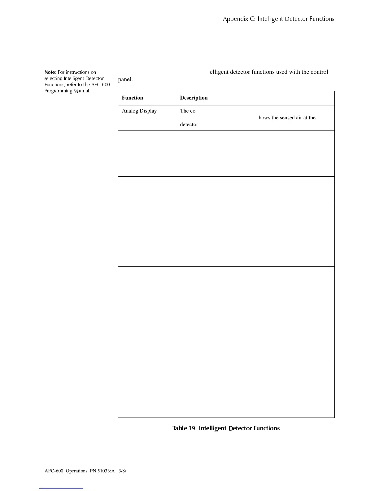
Table 39 contains descriptions for intelligent detector functions used with the control
panel.
7DEOH ,QWHOOL
HQW 'HWHFWRU )XQFWLRQV
Function Description
Analog Display The control panel reads and displays analog information from the
318 analog detectors. The display shows the sensed air at the
detector as a percentage of the alarm threshold for each detector.
Sensitivity Adjust Nine selections for manually setting intelligent detector alarm
levels within the UL range
If using Ionization detectors in duct
applications, set Sensitivity Adjust to Level 1.
Note
: Refer to the AFC-600 Programming Manual for detector
sensitivity information.
Day/Night Sensitivity
Operation
You can program the system to automatically force smoke detectors
to minimum sensitivity during the day. Refer to "Time, Date, and
Holiday Functions" on page 74.
Maintenance Alert When compensation reaches the limit of the amount of drift
compensation that can be safely applied, the control panel reports a
special trouble condition, according to National Fire Alarm Code
standards. This condition also activates if the detector remains at
very high or very low measured air levels for an extended time.
Automatic Test
Operation
The control panel performs an automatic test of each detector every
256 minutes. Failure to meet the test limits causes an Auto Test Fail
trouble.
Type Code
Supervision
The control panel monitors hardware device Type Codes (CPX,
SDX, FDX, LPX, IPX, MMX, CMX, FSI-751, FSP-751, FSP-
751T, FSD-751, FSL-751, FSM-751, FST-751, FST-751R, FMM-1,
FSM-1, FMM-101, FZM-1, FCM-1, and FRM-1) for each installed
device at regular intervals (an interval can take up to 30 minutes for
a full capacity system). If a mismatch of type compared to the
program occurs, the control panel generates a point trouble labelled
Invalid Type.
LED Control
Operation
A global program selection to prevent detector LEDs from blinking
as a result of polling during normal operation. A typical application
is a sleeping area where a blinking light can distract people. As a
standard function, independent of this programming selection, the
control panel allows all LEDs to turn on in alarm.
Alarm Verification
Timer and Verification
Counter Operation
The control panel performs alarm verification on programmed
CPX, SDX LPX, and IPX intelligent smoke detectors. The Alarm
Verification Timer is a global program selection of 0–30 seconds.
Each detector includes a Verification Counter, which displays the
number of times that a detector entered verification but did not
time-out to alarm. The Verification Counter increments to 99 and
holds.
Technical Manuals Online! - http://www.tech-man.com