3-4
CHAPTER 3 REPAIR PROCEDURES
When the Analytical Load Cell Assembly (9) has been
repaired either an Upper or lower Flexure Arm Assembly or
Vertical Flexure has been replaced, it may be necessary to
adjust the Position Sensor. Refer to Figures 3-2, 5-3 and 5-4.
1.Remove the Analytical Load Cell from the bal-
ance, see paragraph 3.1.1.
2.Plug the Position Sensor PCB Assembly Cable
into the Main PC Board (11). Connect all cables
and ensure the Pan is in place.
3.Apply power to the balance.
4.Observe the weight display. Move the Position
Sensor PCB until the display shows numbers.
Carefully tighten the adjustment screws.
5.Reassemble the balance, follow the procedure in
paragraph 3.1.2.
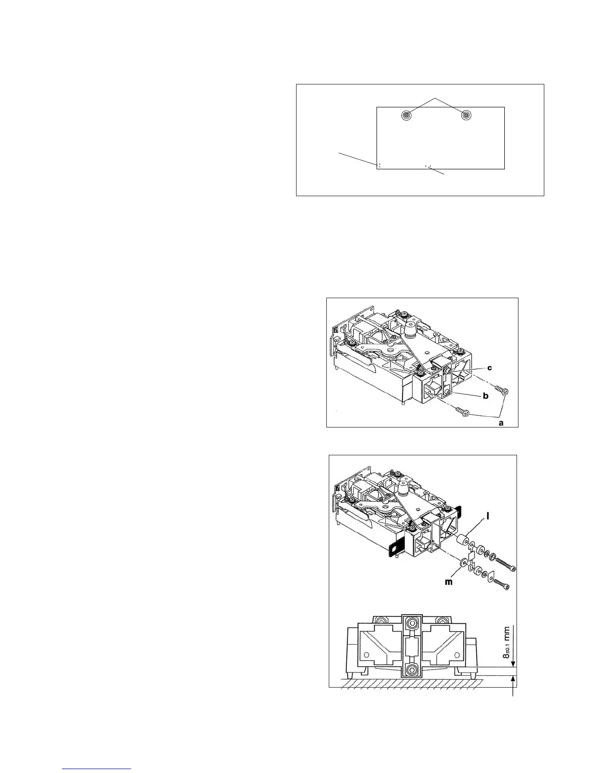
Figure 3-2. Analytical Sensor Board Adjustment
Locations and Connections.
ADJUSTMENT SCREWS
SENSOR PC BOARD
RECISION RESISTOR
CONNECTIONS
SENSOR CABLE
CONNECTIONS
3.1.5 Analytical Load Cell Load Flexure
(Vertical Link) Removal
1.To protect the Flexure at the Hanger, loosely insert
two mounting screws (a). Do not tighten.
2.Loosen the lower flexure screw while holding the
Torsion Protector (b).
3.Unscrew the upper screw (c).
4.Unscrew the lower screw and remove the flexure
and spacers.
Figure 3-3. Removing the Vertical Flexure.
3.1.4 Analytical Load Cell Position Sensor Adjustment Without Test Points
3.1.6 Analytical Load Cell Load Flexure
(Vertical Link) Installation
1.Set the Load Cell on the sensor board.
2.Place the large Spacer (l) on the lever
3.Place the small Spacer (m) on the Hanger.
4.Lay the Flexure on the Spacers with the round hole
at the top. The flexure should be aligned vertically
5.Tighten the upper screw.
6.Insert the lower flexure screw but do not tighten.
Make sure the Torsion Protector is installed.
7.Loosen screws (a) Fig 3-3 and remove the shims.
8.Adjust the height of the hanger to 8 mm / 0.315 in.
9.Tighten the lower flexure screw insuring that the
torsion protector in touching the side of the hanger.
Refer to Figure 3-3.
Figure 3-4. Installing Vertical Flexure.
Refer to Figure 3-4.