3-16
CHAPTER 3 REPAIR PROCEDURES
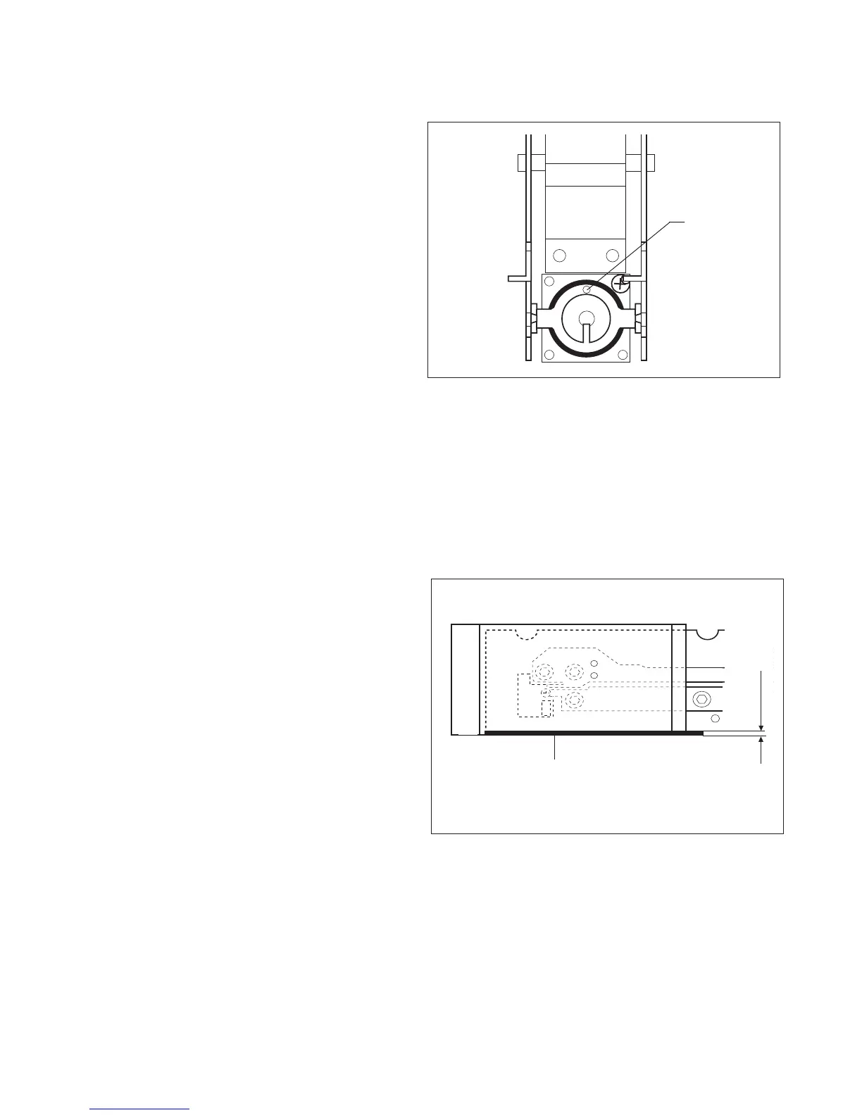
3.1.24 Installing the Force Coil Lever Assembly in Monoblock for High Capacity Top
Loader Balance
Figure 3-22. Force Coil Lever Installation.
1.Place Lever in designated position: check that
the aluminum sleeves are properly positioned.
2.Turn back height adjustment screw to original
position.
3.Insert Centering Pins in holes provided.
4.Insert Lever fastener screws and tighten care-
fully. Ensure that the Lever remains in the
middle at the front.
5.Mount Cover Plate (align at centering pin (g)).
6. Place Position Sensor on the Coil housing.
7.Insert the three screws and tighten with the
nuts.
8.Adjust Position Sensor as described in 3.1.27.
3.1.25 Installing Monoblock and Assembling Position Sensor for High Capacity Top
Loader Balance
1.Place Monoblock and formed chassis turned
by 180 degrees on a flat and clean bench
surface.
2.Screw Monoblock to formed chassis. Ensure
top edge of formed chassis is flush with the top
of the Monoblock. See Figure 3-23.
NOTE:
Tightening torque: 4.0 Nm.
3.Install Calibration Motor (eccentric in top posi-
tion) and Calibration Bracket. During installa-
tion, ensure that there is sufficient play be-
tween the eccentric of the Motor and the Cali-
bration Bracket.
4.Ensure that the Calibration Motor is in the top
position, then insert Calibration weights. Align
Calibration Weight Holders parallel with the
edge of the frame profile and screw firmly so
that a slight pressure causes the Holders to rest
on the Weights.
Figure 3-23. Installation Monoblock and
Position Sensor.
g
i
h
0.5 mm