3-23
CHAPTER 3 REPAIR PROCEDURES
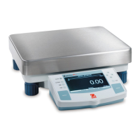
3.2.4 High Capacity Top Loader Balances Main Printed Circuit Board (PCB) and Power
Supply ( PCB)
Refer to Figure 5-6 in Chapter 5 for location of components called out in this procedure. There are two printed circuit boards;
one is the Main PCB and the other is a Power Supply PCB. To remove the boards, proceed as follows:
1.With the balance turned OFF and unplugged, remove the Pan (1).
2.Remove four Pan Mounts (2).
3.Remove three Cover Housing Screws (3) and one screw (37) which secures the Housing Cover (4) to Base
(19).
4.Disconnect the Coil Cable Connector (8), the Internal Calibration Cable (38) (if supplied) and the Cell Cable
Connector (9) from the Main PCB (6).
5.Remove the two Protective Plate Screws (5) holding the Main PCB (6) and Power Supply PCB (7).
6.Carefully lift both PC boards upwards and disconnect Connector PCB Cable (10) from the Power Supply PCB
(7).
7.To separate the PC boards, diconnect the short Main PCB Cable (11) from the Main PCB (6).
8.If the Main PCB is being replaced, the following components must be removed from the defective PCB and
installed on the replacement PCB.
IC1 EPROM
IC16 EPROM
If the Power Supply PCB is being replaced, replace the following components:
IC8 EPROM
IC3 EEPROM
IC12 IC
NOTE: When replacing the PC boards, you will notice two grooves in the Base (19). The PC boards must be
properly seated in these grooves when being replaced.
9.Connect Connector PCB Cable (10) located in the Base (19) to the Power Supply PCB (7).
10. Facing the front of the balance, insert the Power Supply PCB (7) into the slot closest to the left side of the
balance. The holes on the metal shield on the Power Supply PCB (7) should line up with the mounting holes
on the Base (19).
11. Still facing the front of the balance, insert the replacement Main PCB in the remaining groove in the Base (19).
Make sure the short Main PCB Cable (11) from the Power Supply PCB (7) passes through the access hole
on the Main PCB. The holes on the shield on the Main PCB should line up over the holes on the Power Supply
PCB.
12. Install the two Protective Plate Screws (5) holding the Main PCB (6) and Power Supply PCB (7).
13. Connect the Coil Cable Connector (8), Internal Calibration Assembly Cable (38) (if supplied) and the Cell
Cable Connector (9) to the Main PCB (6).
14. Replace three Cover Housing Screws (3) and one screw (37) which secures the Housing Cover (4) to Base
(19).
15. Install four Pan Mounts (2).
16. Install the Pan (1) and apply power to the balance.