3-26
CHAPTER 3 REPAIR PROCEDURES
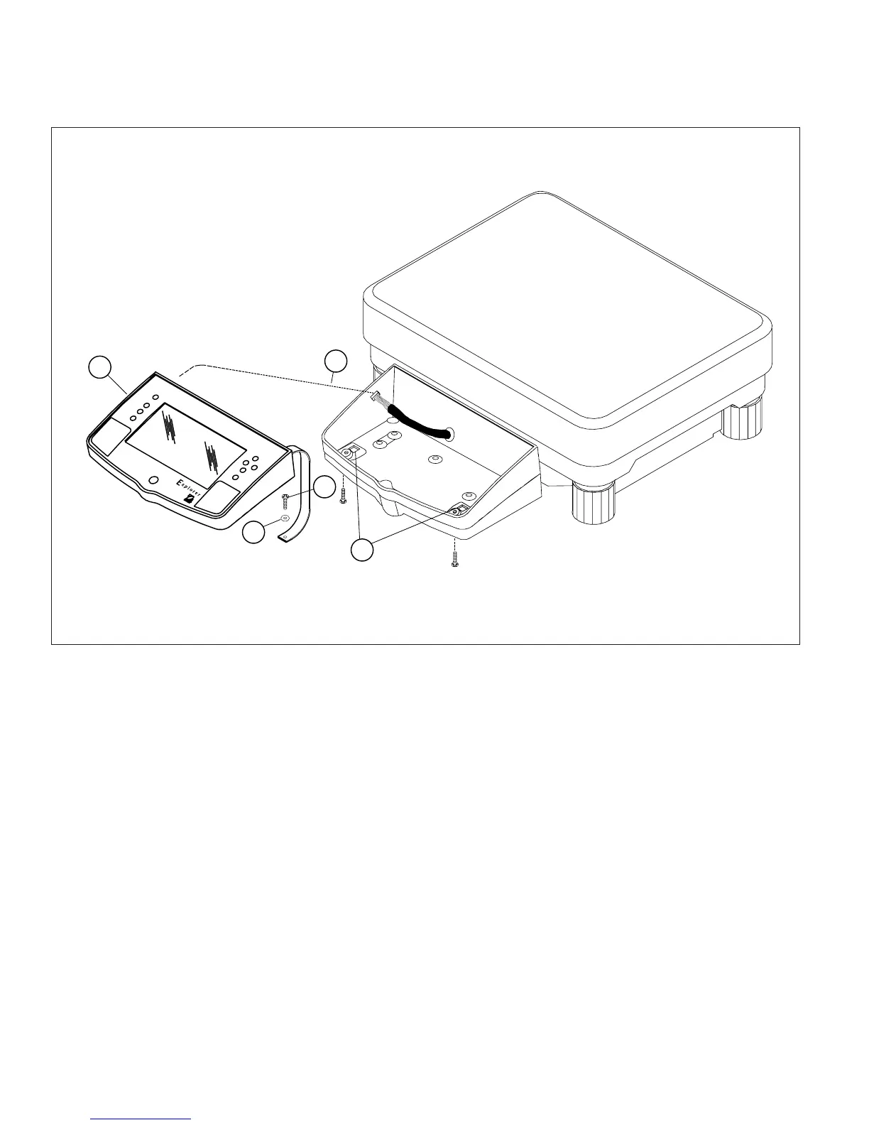
3.2.7 Removing the Display Module on Explorer High Capacity Top Loader Balances
(Cont.)
Figure 3-27. Display Removal/Installation for Explorer High Capacity Top Loader Balance.
3.2.8 Display Printed Circuit Board
>O/T<
>O/T<
1
2
3
4
5
1.Remove the Display Module as per paragraph 3.2.6 or 3.2.7 depending upon type of balance.
2.Turn Display Module over exposing Display PCB Assembly. See Figure 3-28.
3.Carefully unplug the Membrane Panel Switch Ribbon Cable from the Display PCB Assembly Connector.
4.Press the two plastic Clips which hold the Display PCB Assembly in place outward to release the Display PCB
Assembly and remove the PCB Assembly.
5.Position the replacement Display PCB Assembly in place, make sure the Membrane Switch Ribbon Cable
passes through the hole on the Display PCB Assembly, then press the Display PCB Assembly in place. The Clips
should grasp the Board.
6.Grasp the loose end of the Membrane Switch Ribbon Cable on the Display PCB Assembly and insert into the
connector on the Display PCB Assembly.
7.Plug the ribbon cable from the balance Main PCB Assembly into the connector on the end of the Display PCB
Assembly.