3-24
CHAPTER 3 REPAIR PROCEDURES
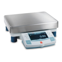
3.2.5 High Capacity Top Loader Balances Connector Printed Circuit Board (PCB)
Refer to Figure 5-6 in Chapter 5 for location of components called out in this procedure. The Connector PCB is located
on the left side of the balance. To remove the board, proceed as follows:
1.Unplug the balance.
2.Remove Platform(1). and turn the balance so it stands on the rear portion.
3.Remove the two screws (12) holding the Connector Plate (13) and Connector PCB (14).
4.Remove the four Hex Nut screws (15) which secures the Connector Plate (13) to the Connector PCB (14).
5.Disconnect Connector Board Cable (10) from Connector PCB (14).
6.Disconnect Display Module Cable (16) from the Connector PCB.
7.Replace Connector PCB and connect Display Module cable (16).
8.Connect Connector Board Cable (10) to the Connector PCB.
9.Install the four Hex Nut screws (15) which secures the Connector Plate (13) to the Connector PCB (14).
10. Position the Connector Plate (13) over the holes on the side of the balance and install the two screws (12).
11. Turn the balance in it's proper operating position and install the pan (1).
12. Apply power to the balance.
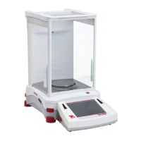
3.2.6 Removing the Display Module on Explorer Precision Top Loader Balances
(See Figure 3-26)
1.Remove power from the balance.
2.Underneath the front of the balance, press the two tabs (1) towards the rear of the balance, this will release
the display.
3.Carefully lift the display (2) up from the balance and swing towards the rear. You will notice a grounding strap
which is screwed into the base of the balance.
4.Remove screw (3) and flat washer (4) from the grounding strap.
5.Carefully unplug the Main PCB Assembly Ribbon Cable (5) from the connector on the Display PCB Assembly
of the display module. Refer to paragraph 3.2.8 for Display PCB replacement.
CAUTION:
BE CAREFUL NOT TO PULL THE RIBBON CABLE OUT OF THE CONNECTOR ON THE MAIN PCB ASSEMBLY INSIDE THE BALANCE.