3-30
CHAPTER 3 REPAIR PROCEDURES
3.2.12 Display PCB/LCD Assembly Replacement
This procedure describes the replacement of either the PCB Assembly or LCD Assembly.
1.Remove the Display module as per paragraph 3.2.11.
2.Turn Display Module over exposing Display PCB Assembly. See Figures 3-31 and 5-9.
3.Carefully unplug the Membrane Panel Switch Ribbon Cable from the Display PCB Assembly Connector.
4.Remove the four, 4 Mounting Screws from Display PCB Assembly and remove the Display PCB Assembly. The
LCD Assembly Board is attached to the Display PCB Assembly with four screws. See Figure 5-9.
5.Turn the Display PCB Assembly over and remove the four screws which mount the LCD Assembly Board to the
Display PCB. Both boards should now be separated. Disconnect the Bulb Connector cable from the Display
PCB Assembly. Either board can now be replaced.
See Appendix D for Bottom Board replacement.
6.See paragraph 3.2.13 for Bulb replacement. If the Bulb is not going to be replaced, continue with this procedure.
7.Assembly both boards together using the four Screws previously removed and reconnect the Bulb Connector.
8.Place the PC boards into position over the four plastic guide posts which are slotted.
9.Screw the four 4 - 40 x 3/16" Mounting Screws into the raised guides and secure both boards.
10. Grasp the loose end of the Membrane Switch Ribbon Cable and insert into the connector on the Display PCB
Assembly.
11. Secure the grounding strap using the hardware previously removed.
12. Plug the ribbon cable from the balance Main PCB Assembly into the connector on the end of the Display PCB
Assembly.
13. Carefully position the display flush with the top of the balance and press into position. The tabs underneath
the balance should lock into place.
14. Reconnect power to the balance.
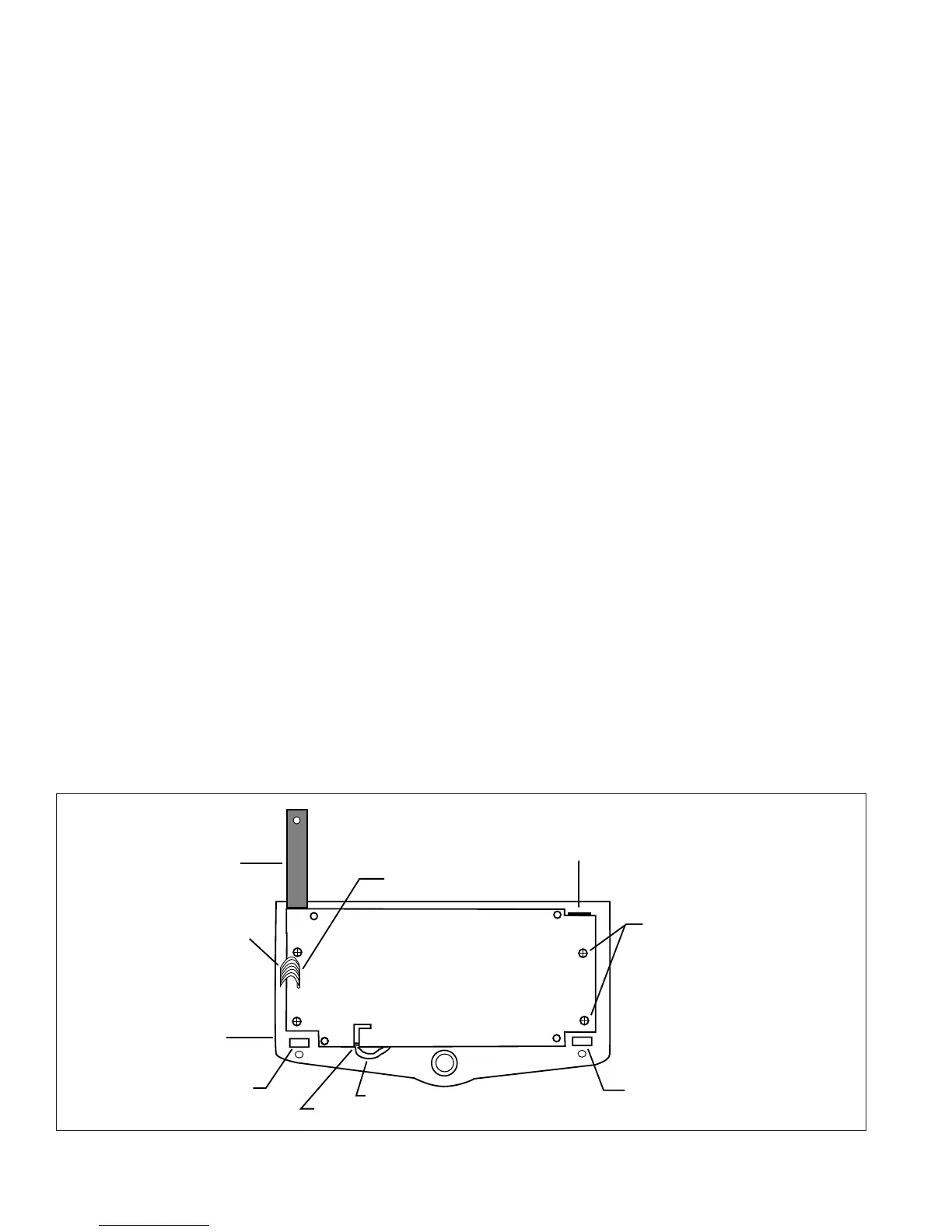
Figure 3-31. Rear View of Display PCB Assembly.
GROUNDING STRAP
BOTTOM OF DISPLAY PCB ASSEMBLY
COVER
RIBBON CABLE CONNECTOR END
COVER CLIP
COVER CLIP
MOUNTING SCREWS
INSERT RIBBON CABLE FROM
MAIN PCB ASSEMBLY
MEMBRANE SWITCH
RIBBON CABLE
WIRES TO BULB ON LCD ASSEMBLY