3-5
CHAPTER 3 REPAIR PROCEDURES
1.At the top of the Load Cell Assembly (51), remove
the two Screws and Washers which secure the
Pan Support to the Hanger.
2.Remove the three screws which secure Bottom
Mounting Plate to Load Cell Base.
3.Remove Vertical Flexure per paragraph 3.1.5.
4.Carefully loosen the two Screws located at the
rear of the Upper Flexure Arm and the rear of the
Lower Flexure Arm (d). These are the screws
which hold the Flexures in place. Do not touch
the two rear most screws with the nuts on top as
these are the adjustment screws.
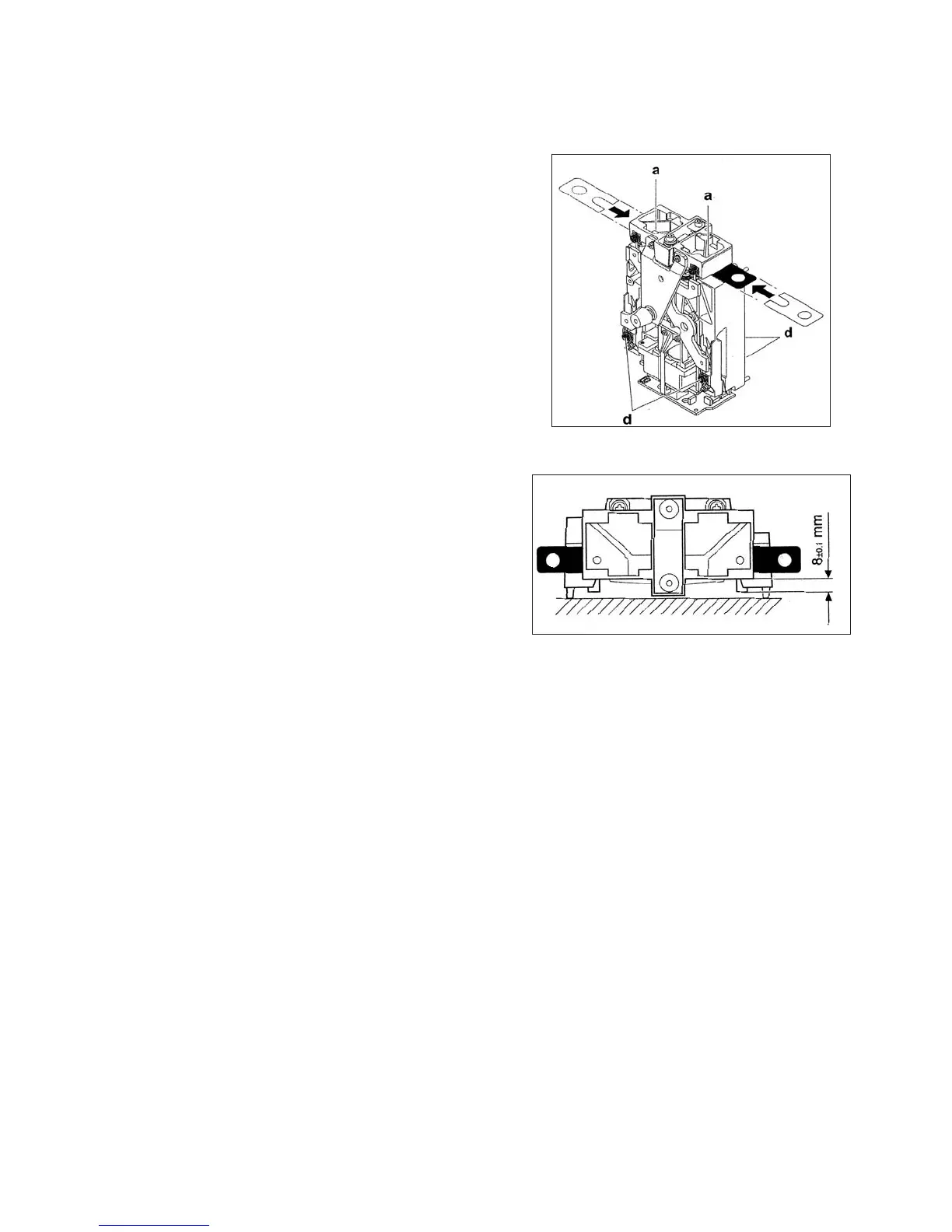
5.At the front of the Load Cell Assembly (51), insert
the two Shims included in kit 476001-02 be-
tween the Hanger and the Load Cell Base with
the open slotted end in first, see Figure 3-5.
The slots should be aligned so that the screw
holes in the Center post to the Load Cell Base are
visible.
3.1.7 Analytical Load Cell Upper Flexure Arm and Lower Flexure Arm Removal/Installation
Refer to Figures 3-5, 3-6 and 5-4 for the following procedure.
CAUTION
Before the Upper or Lower Flexure Arms can
be removed, the the Load Flexure must be
removed and the Hanger secured to the
base of the Transducer with two screws
removed from the Bottom Mounting Plate
(a). This is necessary to prevent further
damage from occuring when trying to re-
move and replace individual Flexures.
6.Take the two Screws removed from the Platform
Mounting Assembly and install them in the Cen-
ter Post through the slots in the Shims. Finger
tighten the screws.
7.Fully tighten the two screws which hold the Shims
in place.
NOTE:
Do not remove the Upper or Lower Flexure Arms
unless there is evidence of damage to one or more
of the Flexure Links.
8.To remove the Upper Flexure Arm from the Load
Cell Assembly (51), remove the four Screws and
Washers, one at each Flexure point.
9.To remove the Lower Flexure Arm from the Load
Cell Assembly (51), remove the four Screws and
Washers, one at each Flexure point.
Figure 3-5. Installing the Shims.
Figure 3-6. Hanger Positioning.
10. Examine each Flexure. Each one must be
perfectly straight. Replace any Flexure which
is bent, twisted, cracked or deformed in any
manner.
11. To replace a defective Flexure, remove the
Screw and Washer which secures the Flexure
to the Upper or Lower Flexure Arm. Replace as
required.
12. To install Upper and or Lower Flexure Arms,
perform steps 8 and 9 in reverse order.
13. Install Vertical Flexure per Paragraph 3.1.4.
14. Remove screws holding Shims and remove
Shims.
15. Secure Pan Support to Center Post with two
screws
16. Install Bottom Mouting Plate with three screws.