3-1
CHAPTER 3 REPAIR PROCEDURES
3.1 REPAIR PROCEDURES
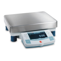
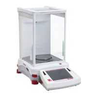
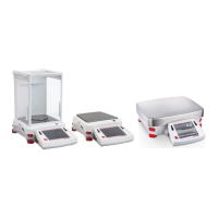
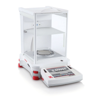
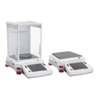
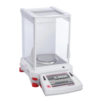
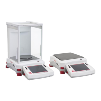
Depending upon the capacity of the balance, one of three different types of load cells are used. The analytical balances
contain an analytical load cell or a Monoblock load cell and the top loader balances contain one of two styles of Monoblock
load cells. This section of the manual contains detailed disassembly and assembly procedures on each of three types of
load cells. The removal of the load cell should only be attempted when it is determined that it requires parts replacement
3.1.1 Analytical Load Cell (9) Removal
Refer to Figures 5-2 and 5-3 in Chapter 5 for location of components called out in this procedure. To remove the Analytical
Load Cell, proceed as follows:
See Figure 5-2 for steps 1 through 4.
1.With the balance turned OFF and unplugged, open the Draft Shield door and remove the Pan (5).
2.Remove Cover Plate (6).
3.Inside of the Draft shield, remove two Screws (2) and Lockswitch Cover Seal (1).
4.Carefully lift the Draft Shield from the balance Base and set aside.
See Figure 5-3 for remaining steps.
5.Remove two Screws (3) which secure Shield (4) in place.
6.Remove Shield (4) from the balance.
7.Remove the two Screws (3) on top of the PC Board (11).
8.Remove the Hex Screws (14) and Washers (25) at the rear of the balance which secure the connectors on
the PC Board (11).
9.Disconnect the two cable connectors from the Load Cell going to J3 and J6 on the PC board as shown on
Figure 5-3.The Load Cell (9). If internal calibration option is installed, disconnect cable to J4.
10. Carefully lift the PC Board (11) from the Base (18) there is a small cable from the Sensor Board which should
also be disconnected from the PC Board (not shown on Figure 5-3).
11. Remove the four screws (8) holding the Internal Calibration Mechanism (10) and lift out the Internal Calibration
Mechanism. Avoid touching the internal calibration mass.
12.Turn the balance over on its side and while holding the Analytical Load Cell with one hand, remove the three
Screws (24) and Washers (23) from the bottom of the balance. The Load Cell can now be removed.
CAUTION
EXTREME CARE MUST BE EXERCISED SO AS NOT TO DAMAGE
THE FLEXURE ARMS FLEXURES, THE RATIO BEAM FLEXURES,
THE LOAD FLEXURE, OR ANY OTHER SUPPORT MEMBER. DAM-
AGE TO ANY ONE OR MORE OF THESE COMPONENTS WILL
DESTROY THE ACCURACY OF THE BALANCE.
NOTE:
Visually inspect the Load Cell Assembly for bent, cracked, or distorted
Flexures. Each Flexure should be perfectly straight. If it is determined
that a Flexure requires replacement, refer to paragraph 4.3.6 for the
Upper Flexure Arm and Lower Flexure Arm removal procedure.