3-22
CHAPTER 3 REPAIR PROCEDURES
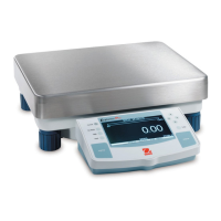
3.2.3 Precision Top Loader Balances Main Printed Circuit Board (PCB) (Cont.)
See Figure 5-3 for remaining steps.
6.Remove the two Hex Screws (1) from the Subplatform (2).
7.Remove the Subplatform (2).
8.Remove two Screws (3) which secure Shield (4) in place.
9.Remove Shield (4) from the balance.
10. Remove the Hex Screws (14) and Washers (25) at the rear of the balance which secure the connectors on
the PC Board (11).
11. Disconnect the two cable connectors from the Load Cell going to J2 and J6 on the PC board as shown on
Figure 5-3.The Load Cell (9). Use cable extenders. If internal calibration option is installed, disconnect cable
to J4.
12. Carefully lift the PC Board (11) from the Base (18) there is a small cable from the Sensor Board which should
also be disconnected from the PC Board (not shown on Figure 5-3).
13. Switch the following components from the defective Main PC Board to the replacement:
U5 EEPROM
U10 - IC
U11 - PSD
14.Install a replacement PC Board.
15.Secure the PC Board (11) to the Base (18) with the two Screws (3).
16.Connect the two cable connectors from the Load Cell (9) to the Main PC Board edge connectors
J2, J6 and the Sensor Cable. The Sensor Board Cable is located at the rear of the balance and may interfere
with the operation of the balance if it is not positioned away from the Load Cell. Dress the cables and make
sure that the cables do not interfere with the Load Cell. If internal calibration option is installed, connect
cable to J4.
17. Install the Hex Screws (14) and Washers (25) at the rear of the balance into the connectors.
18.Install the Shield (4) back on the balance and secure with two Screws (3) (Figure 5-3).
19.Install the Subplatform (2) and secure with two Screws (1).
20.Replace the Cover (14) and and secure with two Screws (2) making sure that the Lockswitch
Cover Seal is in place (Figure 5-1).
21.Replace the four Corner Spacers (13) with the open ends facing out.
22.Replace the Pan (5) and Windshield (12).