4-6
CHAPTER 4 TESTING
Eckenlast abgleichen
+
+
+
+
Position of the test weight Filling position
with + display
400
Viewed From Front of Balance
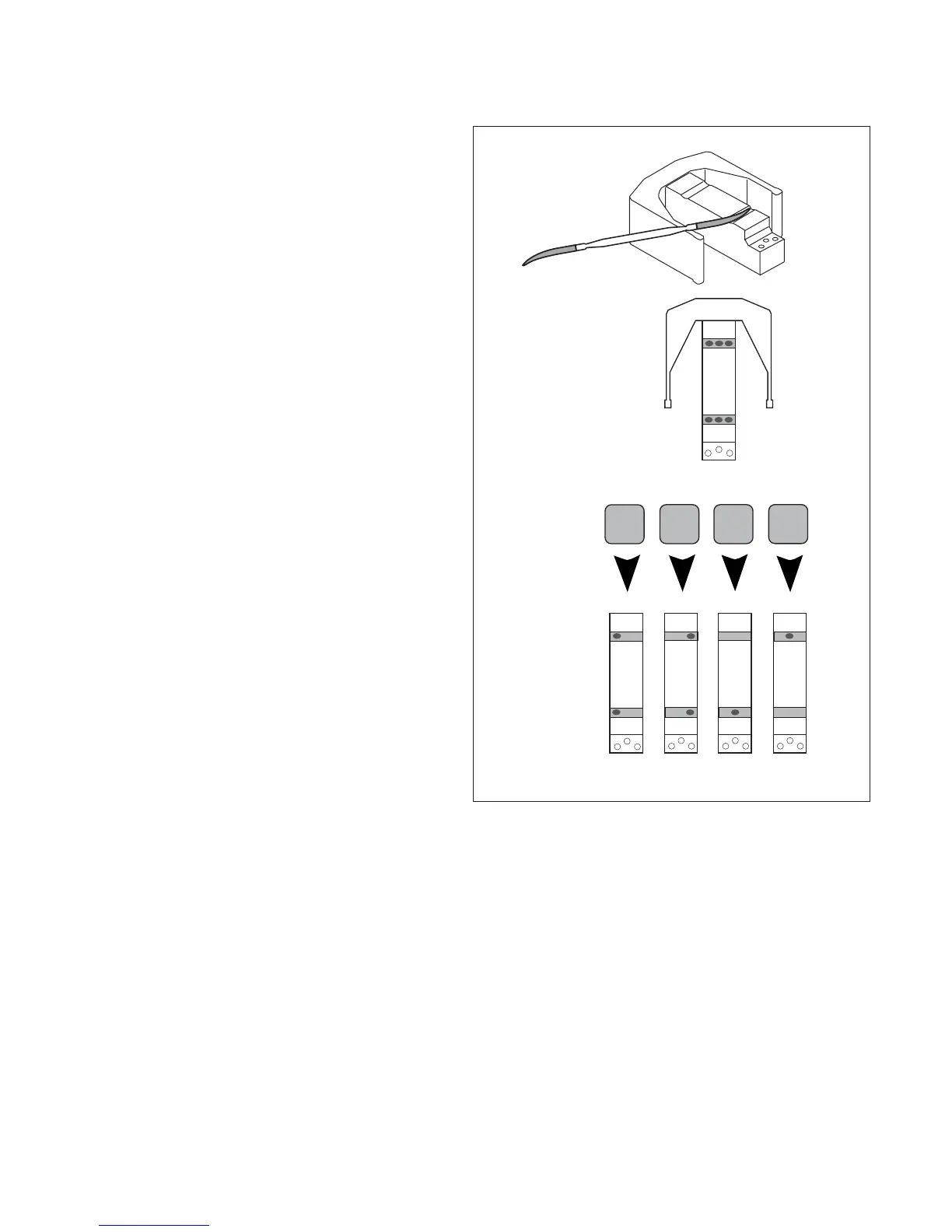
Adjusting the Cornerload on Precision Top
Loader Balances
The Monobloc measuring cell is not adjusted by means of
the cornerload screws, but by removing material from its top.
This is achieved by a few strokes with a nibler file exerting
slight pressure as you pull the file towards you.
CAUTION CAUTION
CAUTION CAUTION
CAUTION:
• Do not attempt to adjust if more than 5 counts out.
• File only in positions shown in Figure 4-6.
• On completion of the adjustments, clean filing sites by
removing residue with adhesive tape. See Figure 5-3 for
following steps.
1.With power removed, install Pan Support (2), and
weighing Pan then apply power.
2.Perform off center load test and determine error.
3.Remove Pan and Pan Support.
4.Determine associated filing position per Figure 4-
10. Perform adjustment as required.
5.Repeat above steps until balance is within
tolerance as per table 4-1.
6.Turn the balance OFF and remove power
7.Remove the Pan and Pan Support (2).
8.Remove cable extenders, connect the two
cable connectors from the Load Cell (9) to the
Main PC Board edge connectors J2, J6 and the
Sensor Cable. The Sensor Board Cable is lo-
cated at the rear of the balance and may
interfere with the operation of the balance if it is
not positioned away from the Load Cell. Dress
the cables and make sure that the cables do
not interfere with the Load Cell. If calibration
option is installed, connect cable to J4.
9.Reinstall the PC Board and secure with two screws (3).
10.Install the Hex Screws (14) and Washers (25) at the rear of the balance which secure the connectors on the
PC Board (11).
11.Install the Shield (4) back on the balance and secure with two Screws (3) (Figure 5-3).
12.Install the Pan Support (2) and secure with two Screws (1).
13.Replace the Cover (6) and and secure with two Screws (3) making sure that the Lockswitch
Cover Seal (4) is in place (Figure 5-1).
14.Replace the four corner pan Spacers (5).
15.Replace the Pan (1) and Windshield (2) if applicable.
Figure 4-6. Monoblock Adjustments.
4.2.2 Off-Center Load Test (Cont.)