8-15
8 Pulse Outputs
CJ2M CPU Unit Pulse I/O Module User’s Manual
8-1 Overview
8
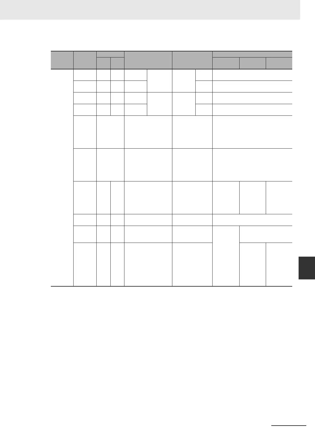
8-1-4 Wiring
z Connections for Pulse Output 2
* Terminals numbers on the XW2D-@@G@ Connector-Terminal Block Conversion Unit.
Pulse I/O
Module
No.
Terminal
symbol
Terminals
Bit Signal
Origin search
Pin (*)
Operation
mode 0
Operation
mode 1
Operation
mode 2
1 (on the
left)
OUT10 31 A16 CIO
2963.00
PV stored
in A322
and A323.
CW/CCW CW Connect to Servo Drive's pulse input
(CW).
OUT11 32 B16 CIO
2963.01
CCW Connect to Servo Drive's pulse input
(CCW).
OUT10 31 A16 CIO
2963.00
PV stored
in A322
and A323.
Pulse and
Direction
Outputs
Pulse Connect to Servo Drive's pulse input
(PULS(886)).
OUT12 33 A17 CIO
2963.02
Direc-
tion
Connect to Servo Drive's pulse input
(SIGN).
--- Normal
input
The external signal
must be received as an
input and the input sta-
tus must be written to
A542.08 in the ladder
program.
CW limit sensor Connect sensor to a normal input termi-
nal.
--- Normal
input
The external signal
must be received as an
input and the input sta-
tus must be written to
A542.09 in the ladder
program.
CCW limit sensor Connect sensor to a normal input termi-
nal.
IN10 1 A1 CIO 2962.00 Origin input Connect to
sensor.
Connect to
the phase-
Z signal
from the
Servo
Drive.
Connect to
the phase-
Z signal
from the
Servo
Drive.
IN11 2 B1 CIO 2962.01 Origin proximity
input
Connect to sensor.
OUT14 35 A18 CIO 2963.04 Error counter reset
output
Not used. Connect to error counter
reset (ECRST) of the
Servo Drive.
IN14 13 A7 CIO 2962.04 Positioning com-
pleted signal (INP)
Not used. Connect to
the posi-
tioning
completed
signal (INP)
from the
Servo
Drive.
 Loading...


