8-17
8 Pulse Outputs
CJ2M CPU Unit Pulse I/O Module User’s Manual
8-1 Overview
8
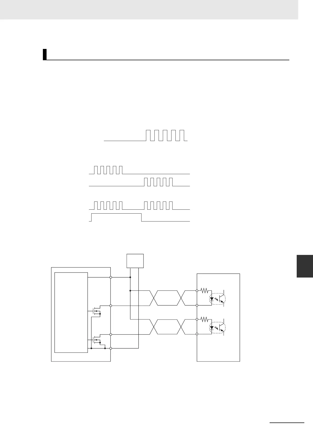
8-1-4 Wiring
This section provides examples of connections to motor drives. Refer to the specifications for the motor
drive being used before actually connecting a motor drive.
The cable length between the Pulse I/O Module and motor drive must not exceed 3 m.
When the pulse output's output transistor is OFF, pulses are not being output.
When the direction output is OFF, it indicates a CCW output.
Do not share the pulse output's power supply (24 VDC or 5 VDC) with any other I/O applications.
z CW/CCW Pulse Outputs and Pulse plus Direction Outputs
• Using a Motor Drive with 24-VDC Photocoupler Inputs
Note The terms in parentheses are for pulse + direction outputs.
Output Connection Examples
Output transistor
Pulse output in progress
CW/CCW Pulse Output
Output ON
Output OFF
Pulse
Direction
CCW
CW
CW
ON
OFF
CW
CCW
CCW
Pulse and Direction Outputs
31/33
(31/32)
37, 38
32/34
(33/34)
39,40
+
−
(+)
(−)
(+)
(−)
Pulse I/O Module (Sinking Outputs)
Input of
power
supply for
outputs
CW pulse
output
(pulse
output)
CCW pulse
output
(direction
output)
24-VDC
power
supply
Motor drive
(24-V input type)
 Loading...


