8 Pulse Outputs
8-18
CJ2M CPU Unit Pulse I/O Module User’s Manual
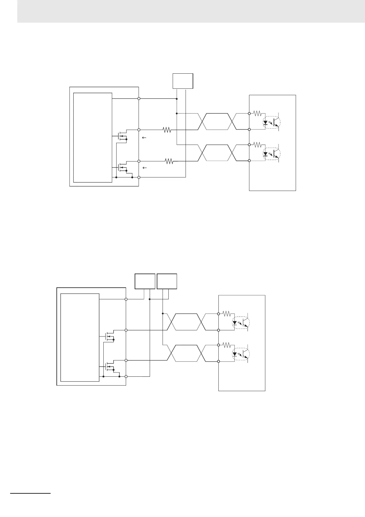
z Using a Motor Drive with 5-VDC Photocoupler Input
• Connection Example 1
Note The terms in parentheses are for pulse + direction outputs.
In this example, the 24-VDC power supply is used for the motor drive with 5-V inputs. Verify that the
Position Control Unit's output current will not damage the motor drive's input circuits. Also verify that
the inputs turn ON properly.
Check that the 1.6-kΩ resistors have sufficient power derating.
• Connection Example 2
Note The terms in parentheses are for pulse + direction outputs.
39,40
31/33
(31/32)
37, 38
32/34
(33/34)
1.6 kΩ
1.6 kΩ
−
+
(+)
(−)
(+)
(−)
Pulse I/O Module (Sinking Outputs)
Input of
power
supply for
outputs
CW pulse
output
(pulse
output)
CCW pulse
output
(direction
output)
24-VDC
power
supply
Approx.
12 mA
Motor drive
(5-V input type)
(Example,
R = 220
Ω
)
Approx. 12 mA
31/33
(31/32)
37, 38
32/34
(33/34)
39, 40
++
−−
(+)
(+)
(−)
(−)
Pulse I/O Module (Sinking Outputs)
Input of
power
supply for
outputs
CW pulse
output
(pulse
output)
CCW pulse
output
(direction
output)
24-VDC
power
supply
Motor drive
(5-V input type)
5-VDC
power
supply
 Loading...


