8-19
8 Pulse Outputs
CJ2M CPU Unit Pulse I/O Module User’s Manual
8-1 Overview
8
8-1-4 Wiring
Precautions for Correct UsePrecautions for Correct Use
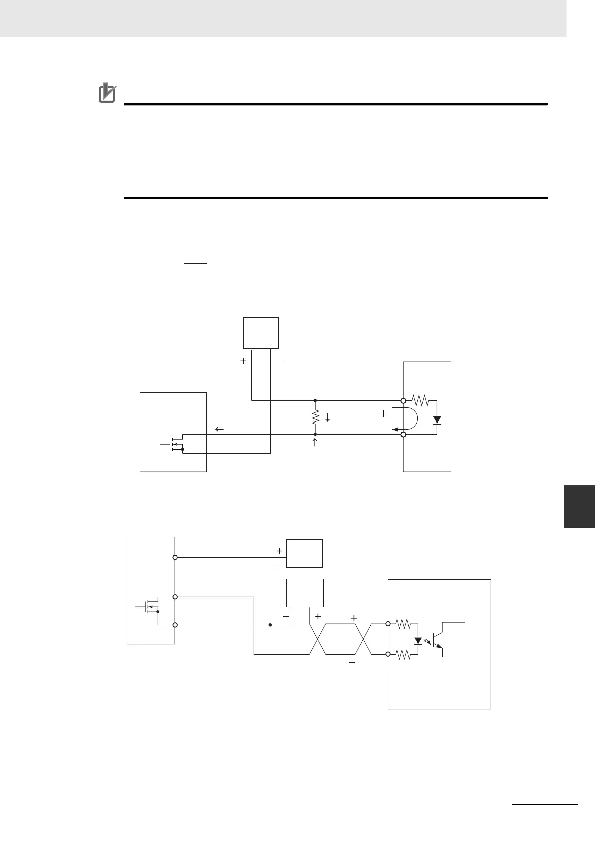
When the output is being used as a pulse output, connect a load that requires an output current
between 7 and 30 mA.
The Unit's internal components may be damaged if the current exceeds 30 mA.
If the current is below 7 mA, the output waveform's rising edge and falling edge will be delayed
and the output frequency ratings may not be met. If the load requires less than 7 mA, install a
bypass resistor so that the circuit draws a current greater than 7 mA (10 mA is recommended.)
Use the following equations to determine the bypass resistor requirements.
z Connection Example for the Error Counter Reset Output
R ≤
V
CC
I
OUT
− I
IN
Power W ≥
R
V
CC
2
× 4 (Tolerance)
V
CC
: Output voltage (V)
I
OUT
: Output current (A)
(7 to 30 mA)
I
IN
: Drive input current
R: Bypass resistance (Ω)
Vcc
I
OUT
R
Circuit Example
I
IN
Pulse I/O Module
(Sinking Outputs)
Power
supply
Servo Drive
Bypass resistor
ECRST
15
14
ECRST
35/36
39, 40
37, 38
Pulse I/O Module
(Sinking Outputs)
Power
supply
input for
outputs
24-VDC
power
supply
5-VDC
power
supply
OMRON R88D-WT Servo
Drive
 Loading...


