8-21
8 Pulse Outputs
CJ2M CPU Unit Pulse I/O Module User’s Manual
8-1 Overview
8
8-1-4 Wiring
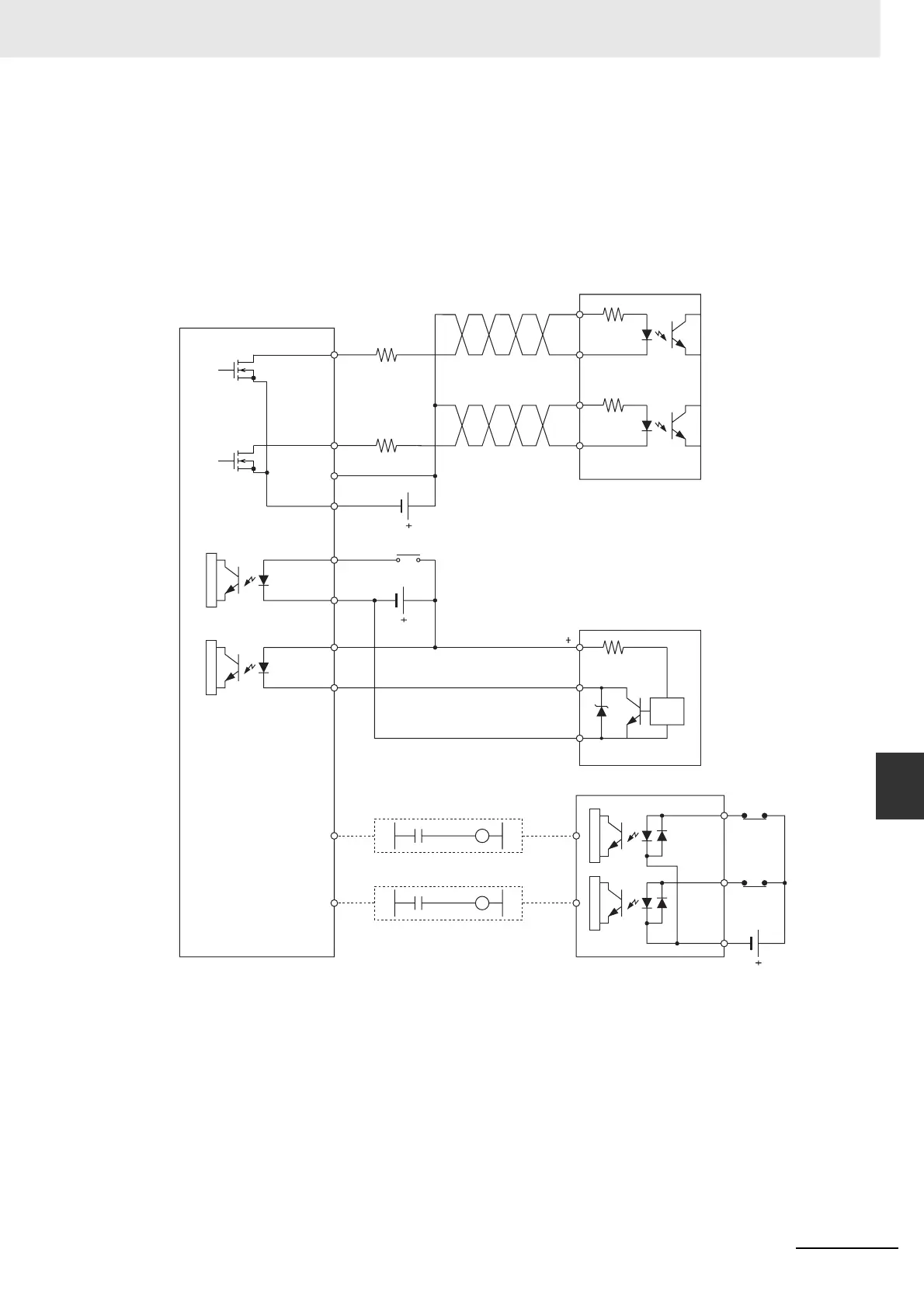
z Connection Example for Operation Mode 0
In operation mode 0, the origin location is determined when the rising edge of the origin input signal
is detected (up-differentiation.) The error counter reset output and positioning completed signal are
not used.
In this example, a stepping motor drive is used and a sensor is connected to the origin input signal
terminal.
31
32
37, 38
A540.09
A540.08
A540.090.01
A540.080.00
0.01
0.00
V
0 V
A8,B8
A0
B0
COM
IN0
IN1
1.6 kΩ
39, 40
1.6 kΩ
24 VDC
+CW
−CW
+CW
−CW
2 (24 V DC)
6 (0 V)
1
(24 VDC)
5 (0 V)
24 VDC
24 VDC
Stepping motor driver
(5-V input type)
CW output
(pulse output 0)
CCW
output
(pulse
output 0)
Power
supply
input for
outputs
Origin Proximity
Input Signal
Origin input
signal
N.O. contacts
E2R-A01 Proximity
Sensor (NPN output)
Output COM
CCW limit
input signal
CW limit
input signal
Signal
Switch
circuit
CJ1W-ID211 Input Unit
N.C.
contacts
N.C.
contacts
Pulse I/O Module (Sinking Outputs)
Operation mode 0
 Loading...


