8 Pulse Outputs
8-22
CJ2M CPU Unit Pulse I/O Module User’s Manual
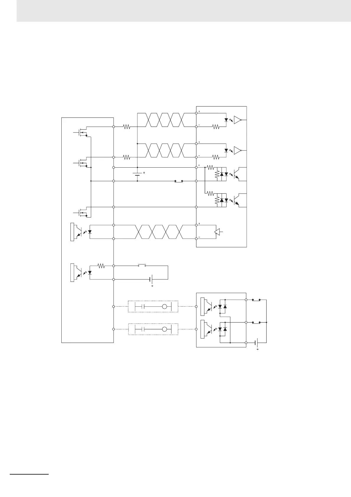
z Connection Example for Operation Mode 1
In operation mode 1, the error counter reset output is turned ON when the origin location is deter-
mined by detection of the rising edge of the origin input signal.
In this example, a servo drive is used and the encoder's phase-Z output is used as the origin input
signal terminal. The servo drive is an OMRON G5-series Servo Drive.
Pulse I/O Module (Sinking Outputs)
Operation mode 1
35
G5-series Servo Drive
3 (LD+)
5 (LD−)
2 (24 VDC)
6 (0 V)
1.6 kΩ
1.6 kΩ
24 VDC
24 VDC
24 VDC
CW output
(pulse output 0)
Power
supply input
for outputs
Output COM
N.C. contacts
Error counter
reset output
Origin input
signal
Encoder's
phase-Z (line
driver output)
Origin
proximity
input signal
N.O. contact
CCW limit
input signal
CW limit
input signal
CJ1W-ID211 Input Unit
N.C.
contacts
N.C.
contacts
CCW output
(pulse
output 0)
A540.09
A540.08
A540.090.01
A540.08
0.00
0.01
0.00
A8,B8
A0
B0
COM
IN0
IN1
31
32
37,38
39,40
CW
3
4
5
6
7
29
30
23
24
Z
Z
CW
CCW
CCW
24VIN
RUN
ECRST
G5-series Servo Drive
 Loading...


