8-25
8 Pulse Outputs
CJ2M CPU Unit Pulse I/O Module User’s Manual
8-1 Overview
8
8-1-4 Wiring
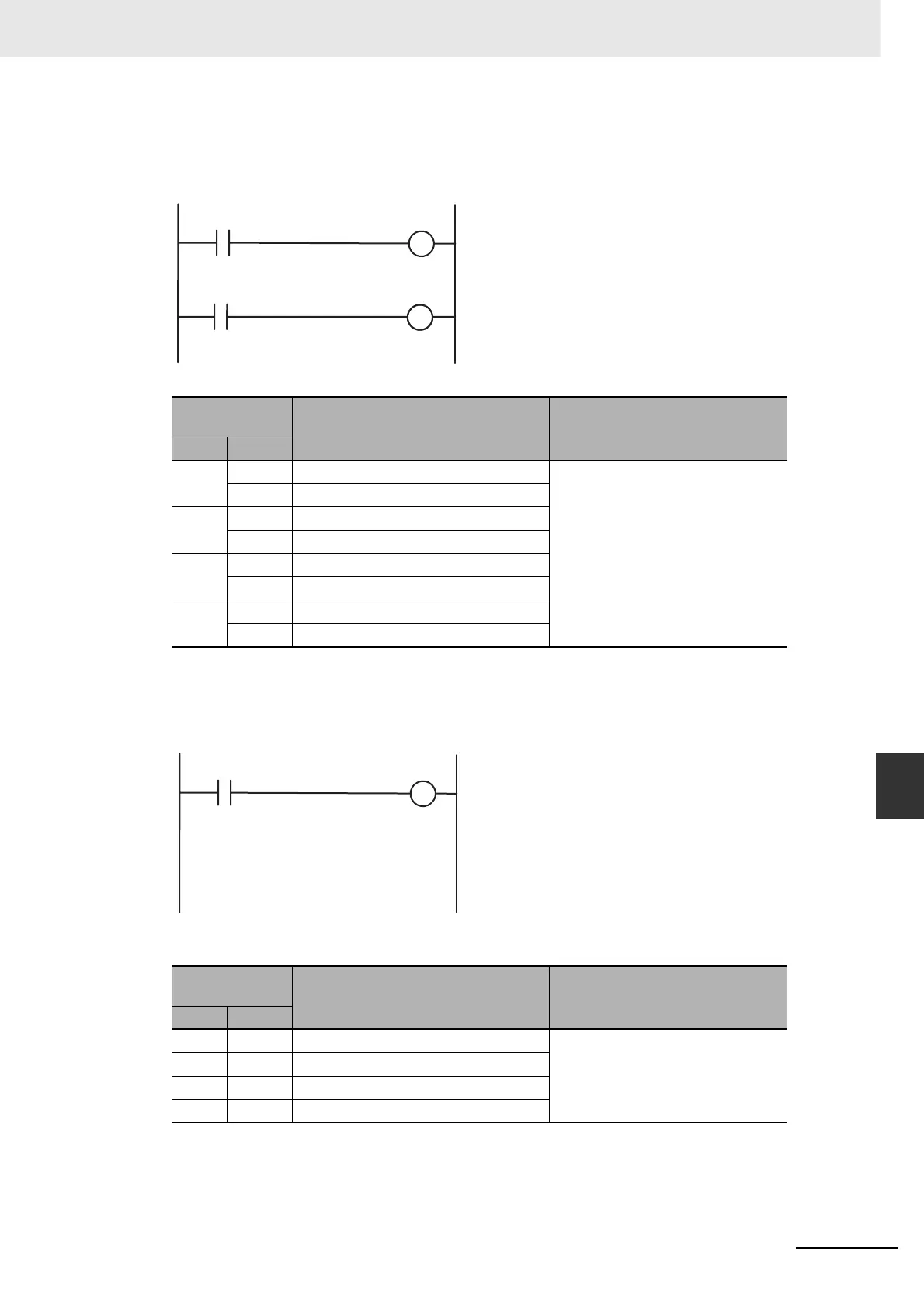
z Outputting to the Auxiliary Area Using the OUT Instruction
The OUT instruction is used in the ladder program to write signals received from the CW limit sensor
and CCW limit sensor connected to normal inputs to the Auxiliary Area bits.
Bits Written in the Auxiliary Area
z Resetting the Pulse Output PV
Each cycle during overseeing processing, the pulse output PVs are reset if ON transitions are
detected in the Reset Bits. The PVs are not cleared, however, if pulses are being output.
Auxiliary Area Bits
Auxiliary Area
bit
Name Function
Word Bit
A540 08 Pulse Output 0 CW Limit Input Signal Signals received from external sen-
sors connected to normal inputs
must be written to the Auxiliary Area
bits in the user program.
09 Pulse Output 0 CCW Limit Input Signal
A541 08 Pulse Output 1 CW Limit Input Signal
09 Pulse Output 1 CCW Limit Input Signal
A542 08 Pulse Output 2 CW Limit Input Signal
09 Pulse Output 2 CCW Limit Input Signal
A543 08 Pulse Output 3 CW Limit Input Signal
09 Pulse Output 3 CCW Limit Input Signal
Auxiliary Area
bit
Name Function
Word Bit
A540 00 Pulse Output 0 Reset Bit The pulse output PV will be cleared
when one of these bits is turned ON.
A541 00 Pulse Output 1 Reset Bit
A542 00 Pulse Output 2 Reset Bit
A543 00 Pulse Output 3 Reset Bit
Normal input from
CW limit sensor
CW limit input signal
A540.08 to A543.08
Normal input from
CCW limit sensor
CCW limit input signal
A540.09 to A543.09
Reset command
Reset Bit
A540.00 to A543.00
 Loading...


