1.4 Setting Switches
1-9
Overview
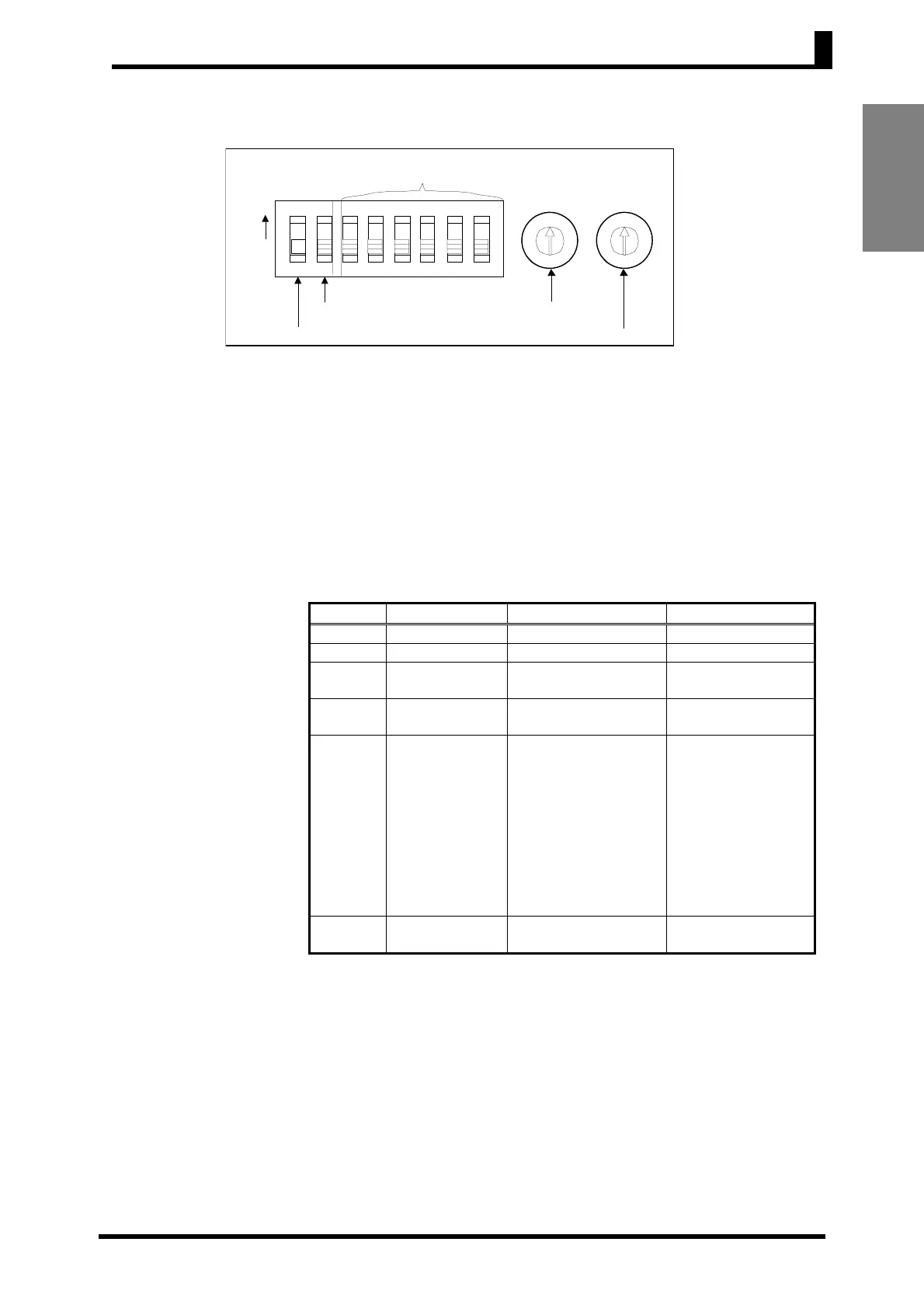
● Protect Switch
• When the protect switch is ON, Up Key and Down Key operations
are prohibited to prevent setting mistakes.
• The Mode Key, however, can also be operated even if the protect
switch is ON.
(The display can be switched between the process value, set point,
alarm value, and input shift value.)
• The default is OFF.
● INIT Switch
• Turn this switch ON when starting from the initial setting level. For
normal operation, make sure this switch is turned OFF.
• Use the control mode switches to make the following operation
settings.
● Control Mode
Switches
Switch Function OFF ON
1 PID ON/OFF ON/OFF control 2-PID control
2 Control period 20 s 2 s
3
Direct/reverse
operation
Reverse operation Direct operation
4
Input shift
display
Disabled Enabled
5
Temperature
Controller
selection
Thermocouple: K, J
Platinum resistance
thermometer:
JPt100
Multi-input:
Thermocouple input
Thermocouple:
K, L
Platinum
resistance
thermometer:
Pt100
Multi-input:
Platinum
resistance
thermometer input
6
Temperature
unit
°
C
°
F
• All switches are OFF for the default settings.
• The hysteresis when using ON/OFF control is 0.2% FS (multi-input
(thermocouple/platinum resistance thermometer) models: 0.1% FS).
• When 2-PID control is set, optimum PID parameters are set
automatically and controlled using ST (self-tuning).
• When the input shift display is disabled, the input shift is not displayed,
but is enabled.
To disable input shift, set the input shift value to H0.
The default setting for the input shift is H0.
• When using thermistor input, the setting for switch 5 is ignored.
ON
1
2
3 4 5 6
ON
INIT switch
Protect switch
P
X
Control mode switches
Temperature ran
e switch
Alarm mode switch
0
4
3
2
1
5
9
8
7
6
0
4
3
2
1
5
9
8
7
6