2.2 Wiring Terminals
2-7
Preparations
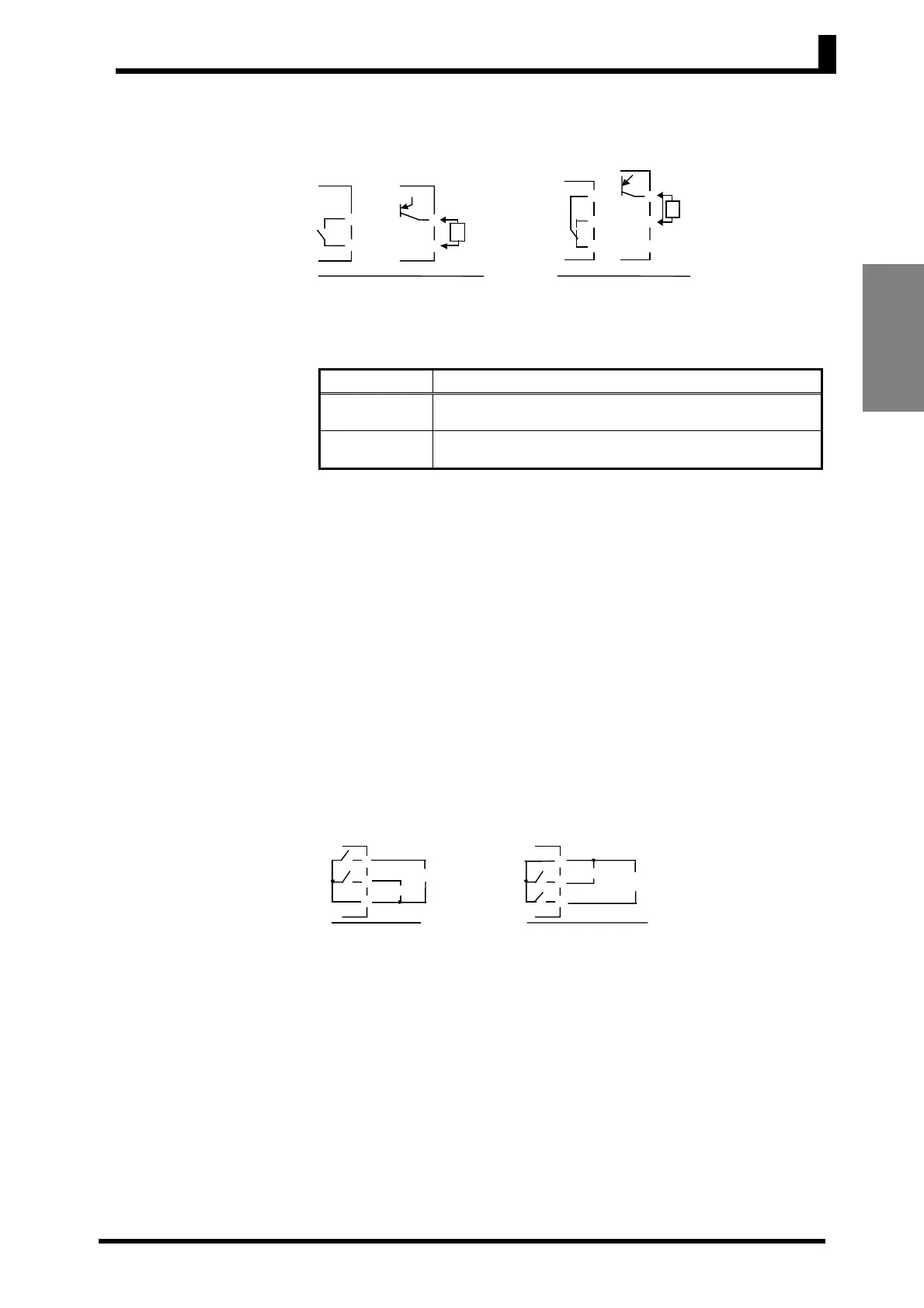
● Control Outputs
• Outputs are sent from terminals 1 and 2 with the E5CSV, and from
terminals 4 to 6 with the E5CS-U. The following diagrams show the
available outputs and their internal equalizing circuits.
• The following table shows the specifications for each output type.
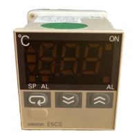
● Alarm Outputs 1
and 2
• With the E5CSV-@1@@-@, alarm output 1 (ALM1) is output across
terminals 7 and 8.
• On the E5CSV-@2@@-@, alarm output 1 (ALM1) is output across
terminals 7 and 8, and alarm output 2 (ALM2) is output across
terminals 6 and 8.
• With the E5CS-@1@@U-@, alarm output 1 (ALM1) is output across
terminals 7 and 8.
• On the E5CS-@2@@U-@, alarm output 1 (ALM1) is output across
terminals 7 and 8, and alarm output 2 (ALM2) is output across
terminals 7 and 9.
• The following diagrams show the internal equalizing circuits for
alarm outputs 1 and 2.
• The relay specifications are as follows:
SPST-NO, 250 VAC, 1 A (resistive load)
Output type
Specifications
Relay
250 VAC, 3A (resistive load), electrical durability:
100,000 operations
Voltage (PNP)
PNP type, 12 VDC
±
15%, 21 mA (with short-circuit
protection)
• A voltage output (control output) is not electrically isolated from the
internal circuits. When using a grounding Sensor, do not connect any
of the control output terminals to the ground. (If control output
terminals are connected to the ground, errors will occur in the
measured temperature values as a result of leakage current.)
E5CS-U
Rela
Voltage
GND
+
-
L
+
v
E5CSV
Rela
Voltage
+
v
L
+
-
GND
E5CS-U
ALM1
ALM2
E5CSV
ALM1
ALM2