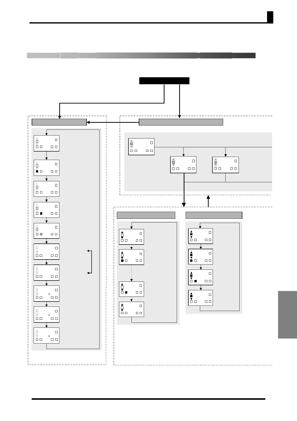
Parameter Flow
A-15
Appendices
Initial setting level (2) Initial setting level (1)
Initial settin
level
No ke
in
ut for 5 s or lon
e
Power ON
SP mode
PV auto reset
PV/SP display
Tuning selection
ST executing display
Manual reset en-
able/disable
Control period selection
(0 to 199)
Initial settin
1
ALM mode
Integral time setting unit
Hysteresis width
Temperature width in which
the
✟
deviation indicator is lit
(0 to 199)
IS mode
ST stable range (1 to
999°C/°F)
1 2ALMALMSP
OUT
--
1 2ALMALMSP
OUT
1
1
1 2ALMALMSP
OUT
1 2ALMALMSP
OUT
Operation level
Initial settin
2
SP mode
Proportional
band (1 to
999
°C/°
F
ALM mode
Integral time (0
to 1,999 s, or 0
to 99 min)
IS mode
Derivative time
(0 to 1,999 s)
1 2
ALMALMSP
OUT
1 2
ALMALMSP
OUT
--
1 2
ALMALMSP
OUT
4
1 2
ALMALMSP
OUT
Process value (1)
PV/SP display: PV→SP
SP mode
Set point
ALM mode
Alarm value 1
ALM2 mode
Alarm value 2
IS mode (1)
Input shift value
(when input shift is
enabled
IS mode (1)
Manual reset value
(when manual reset
is enabled)
IS mode (2)
AT execute/cancel
PV/SP display: No PV
display
IS mode (3)
Alarm 1 latch status
IS mode (4)
Alarm 2 latch status
1
1
2
ALM
ALM
SP
OUT
1
2
ALM
ALM
SP
OUT
1
2
ALM
ALM
SP
OUT
1
2
ALM
ALM
SP
OUT
1
2
ALM
ALM
SP
OUT
t
1
2
ALM
ALM
SP
OUT
h
1
2
ALM
ALM
SP
OUT
h
1
2
ALM
ALM
SP
OUT
1
2
ALM
ALM
SP
OUT
Process value (2)
PV/SP display: SP→PV
Only one
of these
parame-
ters is
displayed.
1
2
ALM
ALM
SP
OUT
Initial setting level selection
--
1 2ALMALMSP
OUT
1 -
-
1
2
ALM
ALM
SP
OUT
--
1 2ALMALMSP
OUT
U
or
D
Key pressed.
Press the
key to move to the
corresponding Initial Setting Level.
Protect switch = OFF
INIT switch = ON
Hold down the
U
Key.
Hold down the
key for 3 s or
longer.
Parameter Flow
This section describes the parameters set in each level. Pressing the M key at the last parameter in
each level returns to the top parameter in that level.