Section 1 Overview
1-8
Overview
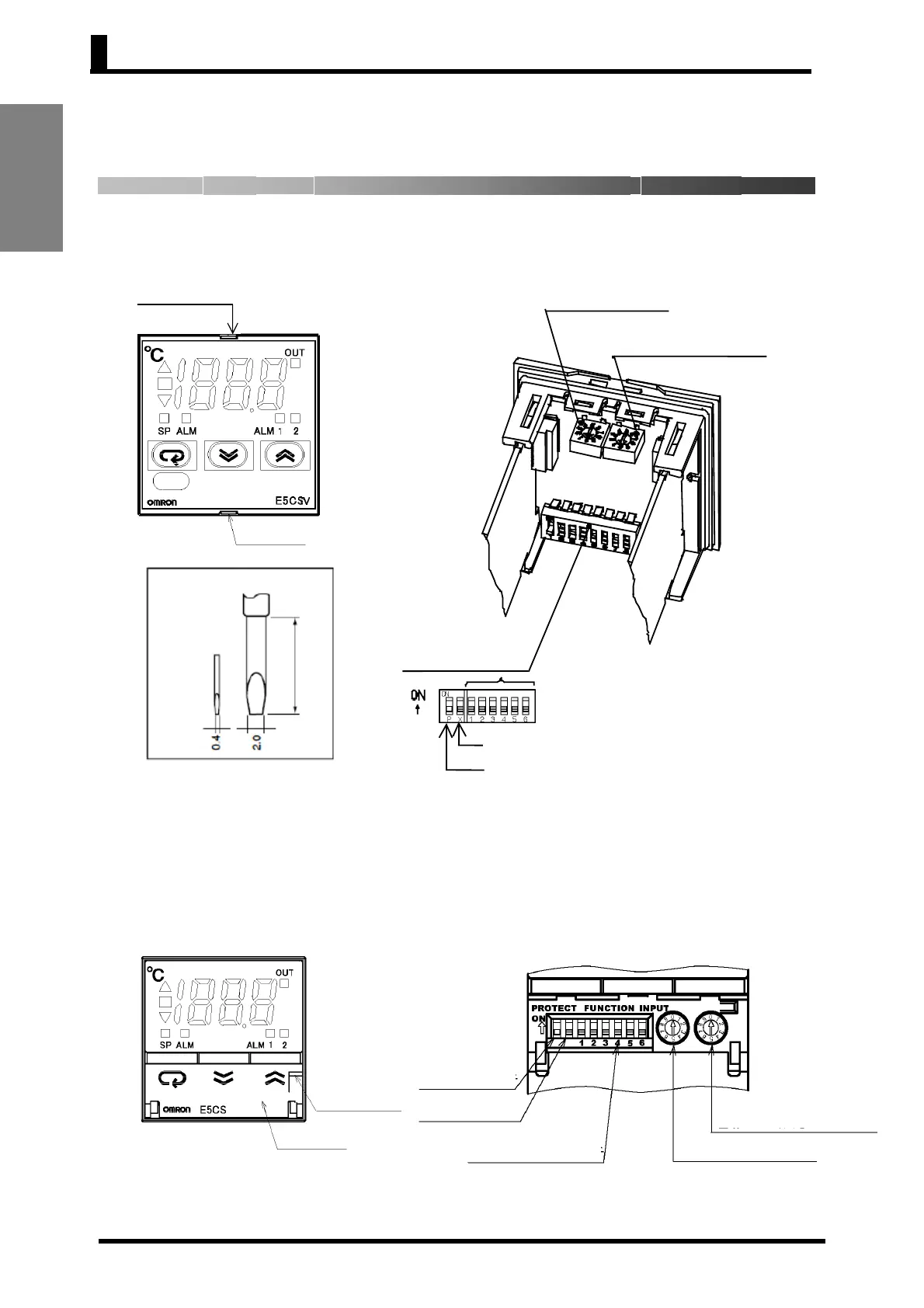
Protect switch
INIT switch *2
Control mode switches
Alarm mode switch *1
Temperature range switch
1.4 Setting Switches
● E5CSV
• Insert the tool (refer to the diagram) into the two tool insertion holes
(one on the top and one on the bottom) and release the hooks. Then,
grip the front panel and pull out towards you to remove it.
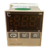
● E5CS-U
• Pull forward on the front door opening/closing groove located on the
right of the front panel and open the front door. Only open the front
door to set the switches. When not setting the switches, always use
the E5CS-U with the front door closed.
*1. The alarm mode switch is not provided on models without alarms.
*2. The INIT switch is always OFF during normal operation.
*1. The alarm mode switch is not provided on models without alarms.
*2. The INIT switch is always OFF during normal operation.
Alarm mode switch *1
Temperature range switch
Control mode switches
INIT switch *2
Protect switch
Flat-blade screwdriver
Unit: mm
20 min.
Front door
opening/closing
roove
Front doo
Tool insertion hole
Tool insertion hole