3.7 Determining PID Constants (AT, ST, Manual Setup)
3-9
Basic
Operations
3.7
Determining PID Constants (AT, ST, Manual Setup)
■ AT (Auto-tuning)
• When AT is executed, the optimum PID constants for the set point at
that time are set automatically. A method (called the limit cycle
method) for forcibly changing the manipulated variable and finding
the characteristics of the control target is employed.
• Auto-tuning (AT) cannot be used during ON/OFF control.
• The AT results are reflected in the “proportional band” (P), “integral
time” (I), and “derivative time” (D) parameters in the initial setting
level (2).
● AT Operations
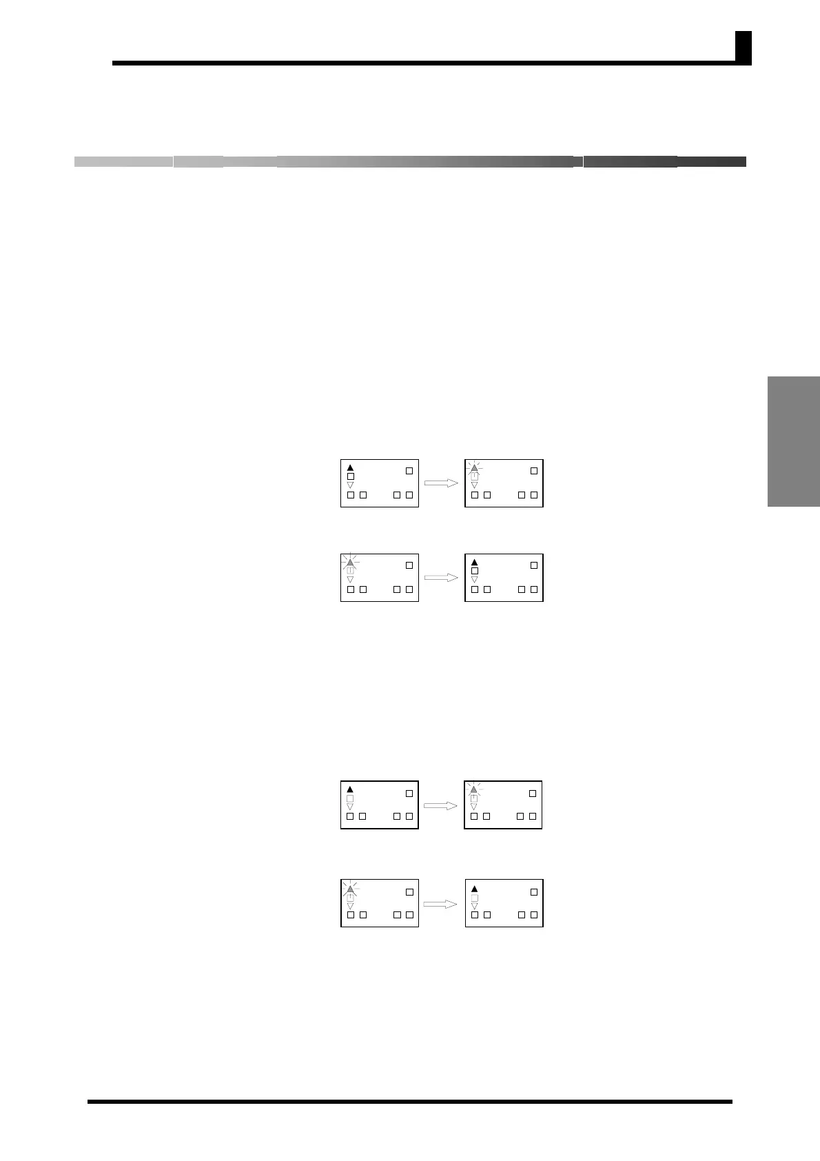
With PV Display
AT (auto-tuning) is executed by pressing the U and D Keys for at
least 2 s while the PV is displayed. The deviation indicators flash
during auto-tuning (AT) execution. AT will be cancelled by performing
the same operation that AT is executing during AT operation. Flashing
stops when AT is completed.
*: One of the deviation indicators (▲■▼) will flash.
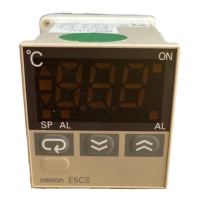
Without PV Display
The “AT execute/cancel” parameter is displayed in the operation
level. Auto-tuning (AT) starts when the “AT execute/cancel”
parameter is set to 1. Auto-tuning (AT) is cancelled when the “AT
execute/cancel” parameter is set to 0 during auto-tuning. When
auto-tuning is completed, the “AT execute/cancel” parameter is
automatically set to 0.
*: One of the deviation indicators (▲■▼) will flash.
AT execution
AT cancelled
0
2
1 2ALMALMSP
OUT
0
2
1
2ALMALMSP
OUT
U+D
Press for at
least 2 s.
AT execution
in progress
0
2
1
2ALMALMSP
OUT
0
2
1
2ALMALMSP
OUT
U+D
Press for at
least 2 s.
AT execution
in progress
AT execution
AT cancelled
0
t.
a
1 2ALMALMSP
OUT
1
t.
a
1 2
ALM
ALMSP
OUT
D
AT execution
in progress
0
t.
a
1 2ALMALMSP
OUT
D
1
t.
a
1 2ALM
ALM
SP
OUT
AT execution
in progress