90
Chapter3 Wiring
F3SJ-A
User’s Manual
Wiring/Installation
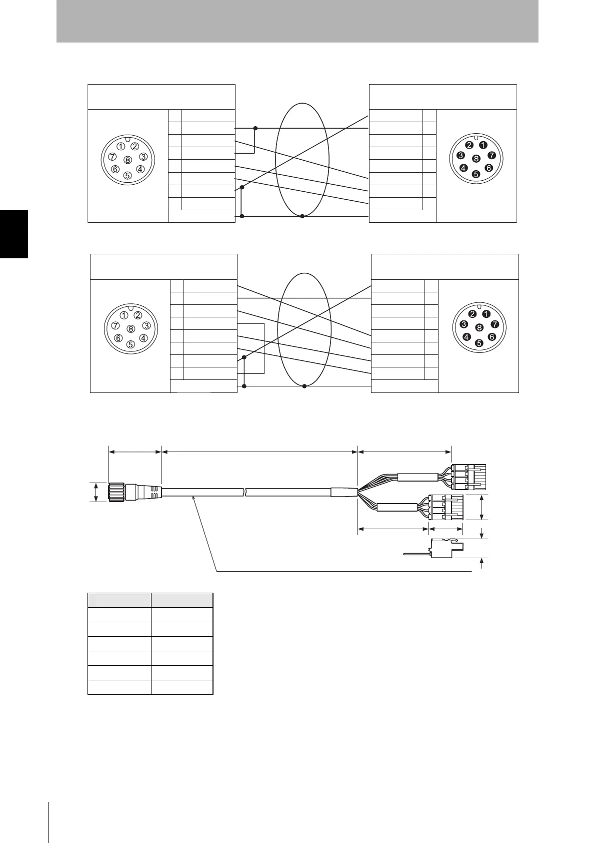
Internal wiring diagram (F39-JCC-L)
Internal wiring diagram (F39-JC-D)
Cable with Connectors on Both Ends: Cable for Connection with F3SX (F39-JCT,
sold separately)
Model name L (mm)
F39-JC1T 1000
F39-JC3T 3000
F39-JC5T 5000
F39-JC7T 7000
F39-JC10T 10000
F39-JC15T 15000
1
2
3
4
5
6
7
8
1
2
3
4
5
6
7
8
-
-
-
-
-
Female
Brown
Green
Yellow
Grey
Pink
Blue
Shield
Grey
Green
Brown
Pink
Blue
Shield
Connected to controller G9SA-300-SC
Male
Connected to emitter's connection cable
and Cable with connectors on both ends
-
-
-
-
1
2
3
4
5
6
7
8
1
2
3
4
5
6
7
8
Female
Brown
Green
White
White
Grey
Pink
Blue
Shield
Grey
Green
Brown
Pink
Blue
Shield
Male
Connected to controller G9SA-300-SC
Connected to receiver's connection cable
and Cable with connectors on both ends
39.5
20
15
L70
53
26
(Unit: mm)
Insulated vinyl round cable dia. 6.6, shielded
8-wire (4-pair) (Cross section of conductor: 0.3mm
2
/insulator diameter: dia. 1.55mm)
dia. 15
Courtesy of CMA/Flodyne/Hydradyne ▪ Motion Control ▪ Hydraulic ▪ Pneumatic ▪ Electrical ▪ Mechanical ▪ (800) 426-5480 ▪ www.cmafh.com

 Loading...


