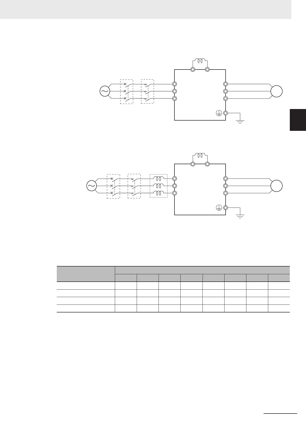
Wiring method
With DC reactor
P(+)
M
P1
L1/R
L2/S
L3/T
U
V
W
MC
MCCB
Power
supply
DC reactor
Three-phase 200 VAC
Single-phase 200 VAC
*1
Three-phase 400 VAC
*1. Connect to the terminals L1/L and L2/N on the single-phase 200-VAC inverter.
With DC reactor and AC reactor
M
P1
P(+)
L1/R
L2/S
L3/T
U
V
W
MC
MCCB
Power
supply
DC reactor
AC reactor
Three-phase 200 VAC
Single-phase 200 VAC
*1
Three-phase 400 VAC
*1. Connect to the terminals L1/L and L2/N on the single-phase 200-VAC inverter.
Effect of reactors
Through the use of the DC/AC reactor, the rate of harmonic current occurrences can be reduced as
shown in the table of typical examples below (excerpt from a JEMA document).
Measure against har-
monics
Harmonic current occurrence rate [%]
5th 7th 11th 13th 17th 19th 23th 25th
None (Inverter only) 65 41 8.5 7.7 4.3 3.1 2.6 1.8
AC reactor 38 14.5 7.4 3.4 3.2 1.9 1.7 1.3
DC reactor 30 13 8.4 5 4.7 3.2 3.0 2.2
With DC and AC reactors 28 9.1 7.2 4.1 3.2 2.4 1.6 1.4
Guideline for reactor selection
When implementing measures against harmonics, first install a DC reactor and evaluate its effect.
Then, if further reduction is required, add an AC reactor.
To implement harmonic countermeasures in consideration of the power supply environment (such
as rapid change in the power supply voltage), first install an AC reactor and evaluate its effect. If
further reduction is required, add a DC reactor.
If you have multiple inverters and use the AC reactor, use one AC reactor for each inverter. Using
only one AC reactor for more than one inverter does not provide sufficient reduction
2 Design
2-47
M1 Series Standard Type User's Manual (I669)
2-3 Wiring
2
2-3-4 Wiring for Main Circuit Terminals
 Loading...


