2-2
Removal of Each Part
2-2-1
Removing Covers
Before wiring each terminal block, you need to remove the surface cover (terminal block cover and the
backing plate).
This section describes how to remove these covers.
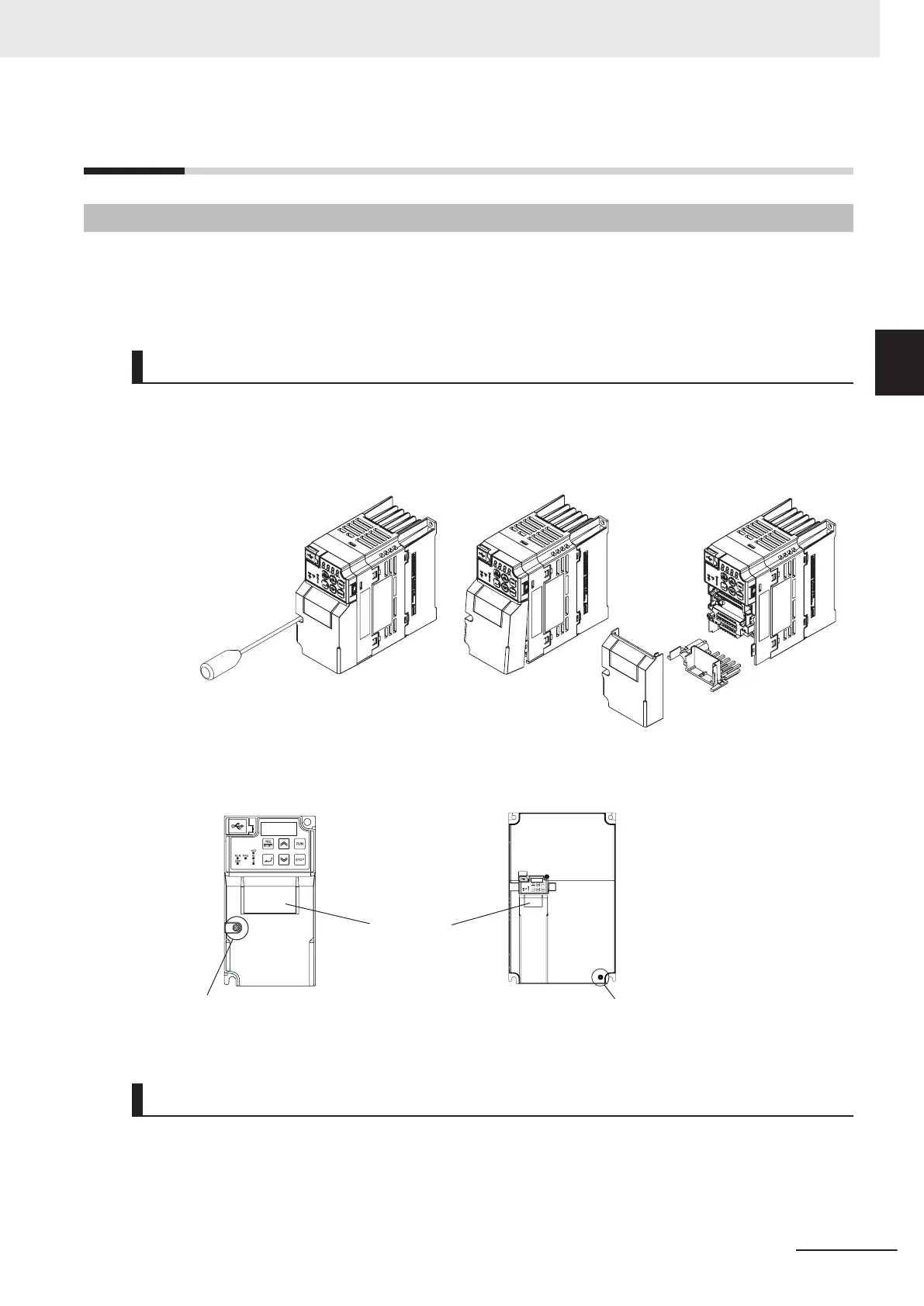
Removing Terminal Block Cover
1 Loosen the terminal block cover fixation screw(s).
2 Remove the terminal block cover from the bottom.
You can find one terminal block cover fixation screw at left center for inverters with a capacity
of 0.75 kW or lower
, center for inverters with a capacity of 1.5 to 15 kW
, and bottom right for
inverters with a capacity of 18.5 kW or higher
.
Terminal block cover
fixation screw
Terminal
block cover
Terminal block cover
fixation screw
Installing Terminal Block Cover
To install the terminal block cover, reverse the removal procedure.
Install the terminal block cover on the inverter from the top and press it until you here a click.
Tighten the terminal block cover fixing screws with the tightening torque of 0.3 Nm.
2 Design
2-7
M1 Series Standard Type User's Manual (I669)
2-2 Removal of Each Part
2
2-2-1 Removing Covers

 Loading...


