4-1
List of Monitors by Group
When monitoring on the Digital Operator, refer to 7-1 Status Monitors on page 7-3.
The following table shows the parameters that allow monitoring of Sysmac Studio.
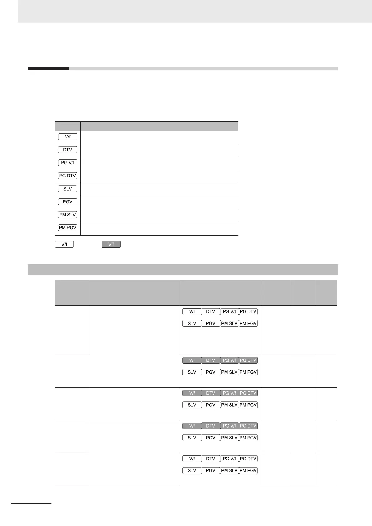
Enabled and disabled states for each control mode within the data range of the parameters are indi-
cated by the icon.
Symbol Control method (F42/A14)
0: IM V/f control
1: IM Dynamic torque vector control
3: IM V/f control with speed sensor
4: IM Dynamic torque vector control with speed sensor
5: IM Vector control without speed sensor
6: IM Vector control with speed sensor
15: PM Vector control without speed and pole position sensor
16: PM Vector control with speed and pole position sensor
: Enabled : Disabled
4-1-1
Parameter M (Monitor 1)
Parameter
No.
Function name Monitor or data range
Default
data
Setting
during
RUN
Unit
M01 Frequency Reference at Final
-32768 to 32767
+20000 or -20000 = maximum
output frequency
0 - -
M02 Torque Reference Monitor at Last
-327.68 to 327.67
0 - %
M03 Torque Current Command at Final
-327.68 to 327.67
0 - %
M04 Magnetic Flux Command Value
-327.68 to 327.67
0 - %
M05 Frequency Reference at Final
0.00 to 655.35
0 - Hz
4 Parameter List
4-2
M1 Series Standard Type User's Manual (I669)

 Loading...


