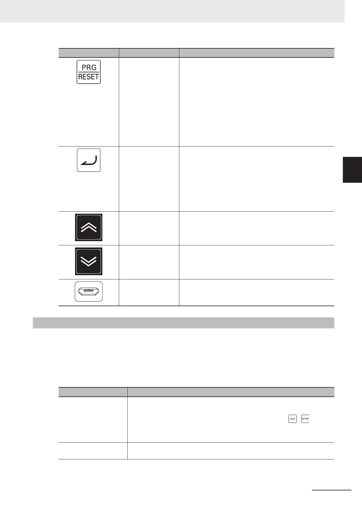
Display Name Description
PRG/RESET key In Operation mode: Pressing this key switches
the mode to the Program
mode.
In Program mode: Pressing this key switches
the mode to the Operation
mode.
In Alarm mode: Pressing this key after remov-
ing the cause of the alarm
cancels the alarm and
switches the mode to the Op-
eration mode.
Enter key In Operation mode: Switches the monitor items
(output frequency, output cur-
rent, output voltage, etc.) for
the operation status.
In Program mode: Confirms the parameter dis-
play and data.
In Alarm mode: Switches to the display of the
alarm details information.
Increment key Increases the parameter number or the set data value.
Decrement key Decreases the parameter number or the set data value.
USB connector The connector (mini-B type) for connecting a computer.
Used to connect to the automation software Sysmac Studio.
3-1-2
Key Operation Method
This section explains how to use the Digital Operator keys in a typical operation (when the Display
Selections “Complete display”).
This operation will be the same even if you select a setting other than Complete display in the Opera-
tor Display Selection (E52), although the number of parameters that you will see on the display differs.
There are three operation modes displayed on the Digital Operator as shown in the following table.
Operation mode Overview of each mode
Operation mode This mode is automatically entered after the power is turned ON.
In this mode, the set frequency/PID process commands and other information can
be set, and RUN/STOP command operations are possible by the / keys.
Operation status can be monitored in real time.
When a light alarm occurs, the display switches to the light alarm display (L-AL).
Program mode In this mode, parameter data can be set, and inverter status, various maintenance
related information and other information can be checked.
3 Operation and Test Run
3-3
M1 Series Standard Type User's Manual (I669)
3-1 Operation of Operator
3
3-1-2 Key Operation Method

 Loading...


